
4 layers63 × 35.6 mm
Kibot variants arduprog
INTI-CMNB/kibot_variants_arduprog
A test/example of how to use KiBot assembly variants
47 parts9MIT

 mot-prog/avr-programmer
Custom In-System Programmer (ISP) for AVR microcontrollers. Built from scratch with an ATmega16U2, LUFA, and libusb.
Programmateur is an open-source printed circuit board by mot-prog, from the mot-prog/avr-programmer repository on GitHub, published under the MIT licence. It is a 2-layer board of 59.4 × 37.1 mm with 29 parts on 35 nets, routed with 189 tracks and 8 vias.
It is built around the ATMEGA8U2-AU. Its parts include 8 resistors, 4 capacitors, 4 diodes, 3 connectors and 2 switches. It belongs with the interfaces and adapters boards and the AVR (ATmega, ATtiny) boards of this library.

Because this was a french project, most of the code was written in French
A custom In-System Programmer (ISP) designed to flash AVR microcontrollers via USB. This project encompasses the full stack: custom hardware design (PCB), USB firmware (LUFA), and a host PC tool (libusb).
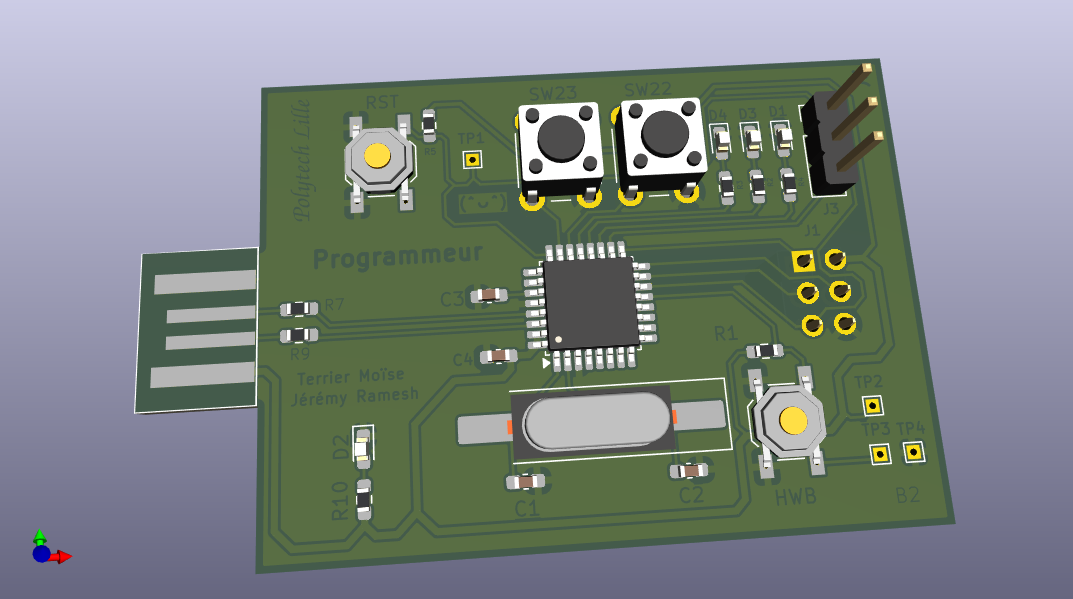
libusb-1.0 to parse Intel HEX files and flash targets directly from a Linux terminal./hardware)The board is built around an ATmega16U2. It exposes a standard ISP interface (MISO, MOSI, SCK, RESET) to connect to target AVRs.
hardware/ directory./firmware)The brain of the programmer. Written in C using the LUFA library.
OUT packets from the PC to execute SPI commands.IN packets./software)A Linux command-line interface written in C.
libusb-1.0..hex files./ISP_tests)Functions to test the hardware by ISP:
blink.c: test the ledsboutons.c: test the boutonsYou need the AVR toolchain and libusb installed on your system:
sudo pacman -S avr-gcc avr-libc avrdude libusbsudo apt-get install gcc-avr avr-libc avrdude libusb-devA root Makefile orchestrates the cross-compilation for both the PC host and the AVR firmware.
# Build firmware, PC software, and test examples
make allConnect the programmer to your PC via USB. Put the ATmega16U2 board into DFU mode (Hardware RESET), then flash the compiled LUFA firmware:
make minicommake progUnplugging and replugging the USB cable it sometimes necessary to detect the AVR with the new firmawre.
Connect the programmer to your PC via USB, and wire the ISP header to your target AVR (e.g., an Arduino Uno / ATmega328P).
1. Where you put your C files
In code_to_flash you put your C files. When you compile all the files (make) your C files are stored in the hex folder.
2. Read Target Flash:
make readUsefull to be sure that the code is properly written into the card
3. Write Hex File to Target:
# Example
make write hex/blind.hex| Qty | Value | Footprint | References |
|---|---|---|---|
| 4 | 510 | Resistor_SMD:R_0603_1608Metric_Pad0.98x0.95mm_HandSolder | R2, R3, R4, R10 |
| 4 | LED | LED_SMD:LED_0603_1608Metric_Pad1.05x0.95mm_HandSolder | D1, D2, D3, D4 |
| 2 | 10k | Resistor_SMD:R_0603_1608Metric_Pad0.98x0.95mm_HandSolder | R1, R5 |
| 2 | 22 | Resistor_SMD:R_0603_1608Metric_Pad0.98x0.95mm_HandSolder | R7, R9 |
| 2 | 22p | Capacitor_SMD:C_0603_1608Metric_Pad1.08x0.95mm_HandSolder | C1, C2 |
| 2 | SW_Push | Button_Switch_SMD:SW_SPST_TL3342 | HWB, RST |
| 2 | SW_Push | Button_Switch_THT:SW_PUSH_6mm_H4.3mm | SW22, SW23 |
| 1 | 100n | Capacitor_SMD:C_0603_1608Metric_Pad1.08x0.95mm_HandSolder | C4 |
| 1 | 1u | Capacitor_SMD:C_0603_1608Metric_Pad1.08x0.95mm_HandSolder | C3 |
| 1 | ATmega8U2-A | Package_QFP:TQFP-32_7x7mm_P0.8mm | U1 |
| 1 | AVR-ISP-6 | Connector_PinSocket_2.54mm:PinSocket_2x03_P2.54mm_Vertical | J1 |
| 1 | Conn_01x03_Pin | Connector_PinHeader_2.54mm:PinHeader_1x03_P2.54mm_Vertical | J3 |
| 1 | Crystal | Crystal:Crystal_SMD_HC49-SD_HandSoldering | Y1 |
| 1 | Ground | TestPoint:TestPoint_THTPad_1.0x1.0mm_Drill0.5mm | TP4 |
| 1 | Hardware Boot | TestPoint:TestPoint_THTPad_1.0x1.0mm_Drill0.5mm | TP3 |
| 1 | Reset | TestPoint:TestPoint_THTPad_1.0x1.0mm_Drill0.5mm | TP1 |
| 1 | USB_A | USB-A:USB-A-PCB | J2 |
| 1 | Vcc | TestPoint:TestPoint_THTPad_1.0x1.0mm_Drill0.5mm | TP2 |
It measures 59.4 × 37.1 mm and has 2 copper layers, 1.6 mm thick.
29 parts, built around the ATMEGA8U2-AU. The full list of its parts is on this page, with links to each part's symbol and footprint where PCBKit's library has them.
From the mot-prog/avr-programmer repository on GitHub, at the commit this page was made from: the board is hardware/programmateur.kicad_pcb and its schematic hardware/programmateur.kicad_sch. PCBKit opens the board in the browser, with nothing to install.
Its repository publishes it under the MIT licence: you may reuse it on that licence's terms (keep the author's notice, and for a copyleft licence share your changes alike).
INTI-CMNB/kibot_variants_arduprog
A test/example of how to use KiBot assembly variants

chanulee/lovelace-ruler
LOVELACE PCB ruler: 55x25 mm reference ruler, KiCad + Figma silkscreen

egeozgul/SnowBOARD
Key features include an integrated SD card slot for data storage, a comprehensive battery power management circuit for portable applications, a USB Type-C interface for modern connectivity, and a built-in USB-to-UART…

INTI-CMNB/kibot_variants_arduprog_site
Example of KiBot navigate results deployment using --quick-start

CRImier/MyKiCad
My KiCad boards. Can't be bothered uploading individually anymore, so here you go.


