2 layers100 × 64 mm
Rf power monitor rev2
TheKingOfChaos/RF-Power-Monitor
A 2-layer carrier board for the WIZnet W5500-EVB-Pico-PoE. It is 80 x 51.5 mm: exactly as long as the module, so both short edges line up with the module.
129 parts

 MostlyWithinSpec/Network-Goblin-ND-2
A Linux-powered handheld network multitool with real cable diagnostics.
Tdr dongle is an open-source printed circuit board by MostlyWithinSpec, from the MostlyWithinSpec/Network-Goblin-ND-2 repository on GitHub. It is a 4-layer board of 70 × 30 mm with 90 parts on 99 nets, routed with 900 tracks and 205 vias.
It is built around the 88E1512-A0-NNP2C000, LAN7801-I/9JX and TLV62569DBVR-TP, with the 93AA66/SN, PRTR5V0U2X,215 and TPD4EUSB30DQAR among its other parts. Its parts include 51 capacitors, 26 resistors, 6 ICs, 2 connectors and 2 inductors. It belongs with the computers and single-board computers boards of this library.


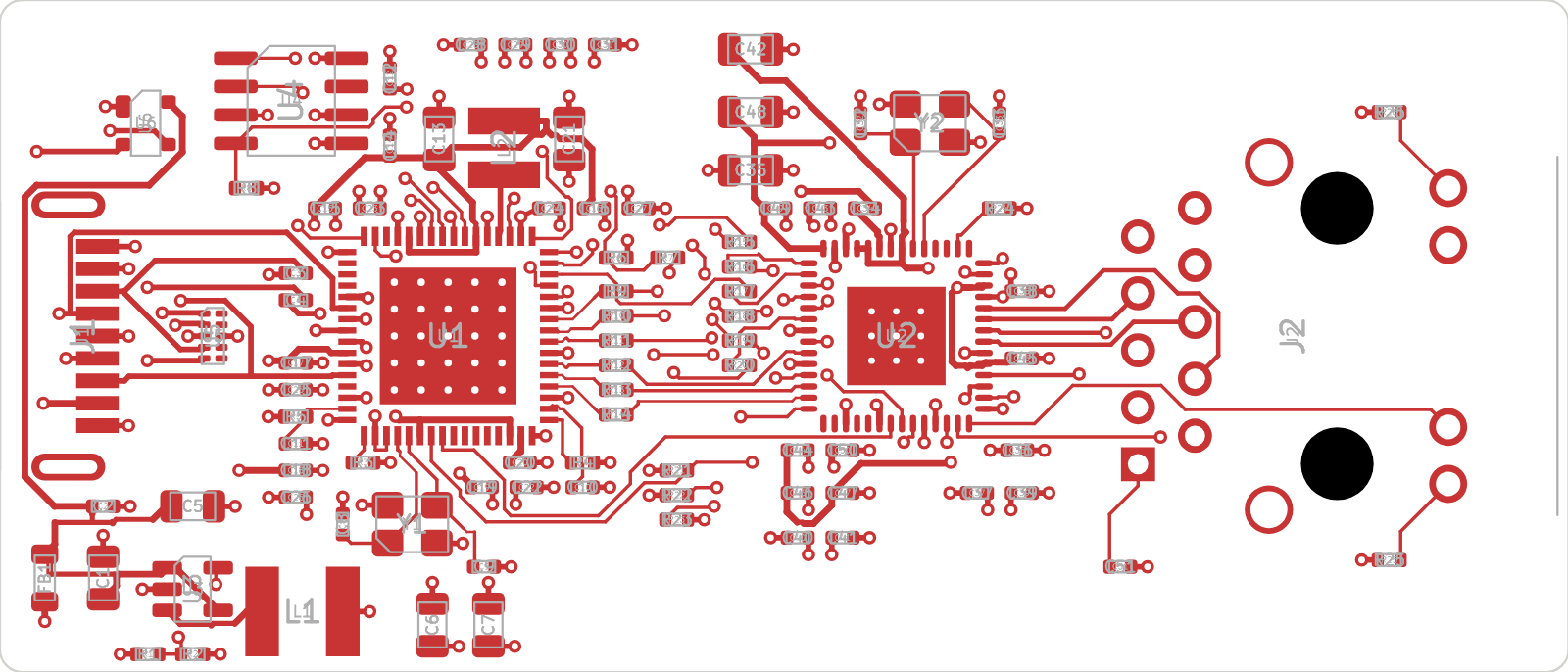
A small USB 3 → Gigabit Ethernet dongle that is just the ND-2 test-port circuit:
Microchip LAN7801 (USB 3 to RGMII MAC) + Marvell 88E1512 (GbE PHY with VCT/TDR) + HanRun 1G magjack.
Plug it into a Pi 5 / CM5 IO board and prove ethtool --cable-test / --cable-test-tdr before building the CM5 carrier.
Status: ERC and DRC clean, schematic/PCB parity clean, ordered from JLCPCB in Sept 2026. Not yet tested on real hardware. Bring-up plan: docs/bring-up.md.
| File | What it is |
|---|---|
tdr-dongle.kicad_sch | Schematic (KiCad 10, one A2 sheet, label-based wiring) |
ND2.kicad_sym + sym-lib-table | Project symbols: ND2:LAN7801, ND2:88E1512, ND2:HR911130C |
ND2.pretty + fp-lib-table | Project footprints (from LCSC/EasyEDA, cleaned up — see below) |
bom_jlcpcb.csv | Grouped BOM in JLCPCB format (Comment, Designator, Footprint, LCSC Part #) |
bom.csv | One line per part with MPN + LCSC |
netlist_report.txt | Every net and the pins on it |
tdr-dongle.kicad_pcb | PCB: 70 x 30 mm, 4-layer |
tdr-dongle.kicad_pro | KiCad project (design rules, net classes) |
tdr-dongle.net | KiCad netlist export |
fab/ | Fabrication package: Gerber zip, JLC BOM + CPL, layer PDF, schematic PDF, STEP, renders |
scripts/ | Python scripts that generated the schematic and PCB (see scripts/README.md) |
| Ref | Part | LCSC | Footprint | Notes |
|---|---|---|---|---|
| U1 | LAN7801-I/9JX | C633491 | ND2:LAN7801_QFN-64-1EP_9x9mm_P0.5mm_EP6.1mm | Only ~13 in stock at LCSC |
| U2 | 88E1512-A0-NNP2C000 | C845579 | ND2:88E1512_QFN-56-1EP_8x8mm_P0.5mm_EP4.4mm | Only ~13 in stock at LCSC |
| U3 | TLV62569DBVR | C141836 | SOT-23-5 | 3V3 buck |
| U4 | 93AA66/SN | C615340 | SOIC-8 | ORG pin (6) tied to GND = 512 x 8 |
| U5 | TPD4EUSB30DQAR | C90627 | USON-10 | USB 3 ESD |
| U6 | PRTR5V0U2X,215 | C12333 | SOT-143 | USB 2 ESD |
| J1 | HC-USB3.0-C26 (USB 3 Type-A plug, SMD) | C7501854 | ND2:USB3_A_Plug_HongCheng_HC-USB3.0-C26 | Flash-drive style plug at the board edge |
| J2 | HanRun HR911130C (1G magjack, 2 LEDs) | C50933 | ND2:RJ45_HanRun_HR911130C_Horizontal | Replaces the Pulse JK0654219NL (0 stock) |
| Y1, Y2 | X322525MOB4SI 25 MHz, CL 12 pF | C9006 | Crystal_SMD_3225-4Pin | Load caps changed to 15 pF |
| L1 | SMNR4020-2.2UH (3.4 A) | C135262 | ND2:L_4.0x4.0mm_SMNR4020 | Buck inductor |
| L2 | SMNR3015-3R3MT (1.32 A) | C135239 | ND2:L_3.0x3.0mm_SMNR3015 | LAN7801 1V2 switcher |
| FB1 | MPZ2012S601AT000 (600 Ω, 2 A) | C21519 | L_0805 | VBUS filter |
| Caps | 100 nF C1525 · 1 µF C52923 · 220 nF C16772 · 15 pF C1548 (0402) · 10 µF C15850 · 22 µF C45783 (0805) | |||
| Resistors (0402, UNI-ROYAL) | 22R C25092 · 330R C25104 · 0R C17168 · 1.5k C25867 · 2k C4109 · 4.99k C25903 · 10k C25744 · 12k C25752 · 100k C25741 · 453k C27009 |
lsusb should show 0424:7801. Program the EEPROM with MAC + HW_CFG (hybrid RGMII delay, CLK125_EN).dmesg should show lan78xx attaching the Marvell 88E1510-family PHY at address 0.ethtool --cable-test ethX and ethtool --cable-test-tdr ethX on known cables (open, short, known lengths).fab/ holds:
tdr-dongle_gerbers_JLC.zip: Gerbers + Excellon drills. Upload this to JLCPCB and pick 4 layers, 1.6 mm, JLC04161H-7628.tdr-dongle_BOM_JLC.csv: the BOM (R7 is DNP and left out).tdr-dongle_CPL_JLC.csv: pick and place (89 parts, all top side, origin at the board's lower-left corner).tdr-dongle_layers.pdf, tdr-dongle_schematic.pdf, tdr-dongle.step, and top/bottom renders for review.Caveats:
| Qty | Value | Footprint | References |
|---|---|---|---|
| 33 | 100nF | Capacitor_SMD:C_0402_1005Metric | C2, C3, C11, C12, C15, C16, C17, C18, C19, C23, C24, C25, C26, C27, C28, C29 +17 |
| 12 | 22R | Resistor_SMD:R_0402_1005Metric | R9, R10, R11, R12, R13, R14, R15, R16, R17, R18, R19, R20 |
| 6 | 10uF | Capacitor_SMD:C_0805_2012Metric | C1, C5, C21, C35, C42, C48 |
| 5 | 10k | Resistor_SMD:R_0402_1005Metric | R5, R6, R8, R22, R23 |
| 4 | 15pF | Capacitor_SMD:C_0402_1005Metric | C8, C9, C32, C33 |
| 4 | 1uF | Capacitor_SMD:C_0402_1005Metric | C10, C14, C20, C22 |
| 3 | 22uF | Capacitor_SMD:C_0805_2012Metric | C6, C7, C13 |
| 2 | 25MHz | Crystal:Crystal_SMD_3225-4Pin_3.2x2.5mm | Y1, Y2 |
| 2 | 330R | Resistor_SMD:R_0402_1005Metric | R25, R26 |
| 1 | 0R | Resistor_SMD:R_0402_1005Metric | R7 |
| 1 | 1.5k | Resistor_SMD:R_0402_1005Metric | R21 |
| 1 | 100k | Resistor_SMD:R_0402_1005Metric | R2 |
| 1 | 12k | Resistor_SMD:R_0402_1005Metric | R3 |
| 1 | 2.2uH | ND2:L_4.0x4.0mm_SMNR4020 | L1 |
| 1 | 220nF | Capacitor_SMD:C_0402_1005Metric | C34 |
| 1 | 2k | Resistor_SMD:R_0402_1005Metric | R4 |
| 1 | 3.3uH | ND2:L_3.0x3.0mm_SMNR3015 | L2 |
| 1 | 4.99k | Resistor_SMD:R_0402_1005Metric | R24 |
| 1 | 453k | Resistor_SMD:R_0402_1005Metric | R1 |
| 1 | 600R | Inductor_SMD:L_0805_2012Metric | FB1 |
| 1 | 88E1512-A0-NNP2C000 | ND2:88E1512_QFN-56-1EP_8x8mm_P0.5mm_EP4.4mm | U2 |
| 1 | 93AA66/SN | Package_SO:SOIC-8_3.9x4.9mm_P1.27mm | U4 |
| 1 | HC-USB3.0-C26 | ND2:USB3_A_Plug_HongCheng_HC-USB3.0-C26 | J1 |
| 1 | HR911130C | ND2:RJ45_HanRun_HR911130C_Horizontal | J2 |
| 1 | LAN7801-I/9JX | ND2:LAN7801_QFN-64-1EP_9x9mm_P0.5mm_EP6.1mm | U1 |
| 1 | PRTR5V0U2X | Package_TO_SOT_SMD:SOT-143 | U6 |
| 1 | TLV62569DBV | Package_TO_SOT_SMD:SOT-23-5 | U3 |
| 1 | TPD4EUSB30 | Package_SON:USON-10_2.5x1.0mm_P0.5mm | U5 |
TheKingOfChaos/RF-Power-Monitor
A 2-layer carrier board for the WIZnet W5500-EVB-Pico-PoE. It is 80 x 51.5 mm: exactly as long as the module, so both short edges line up with the module.


Ains0X1/UART-Wand
It is an open-source, ultra-compact USB-to-Serial converter. It uses the CH340E IC to provide a stable asynchronous serial interface (UART) via a USB-C connector.


jrseti/roboclaw-cm4-dc-dish-controller
Satellite dish controller using a ROBOCLAW-2X15A-OEM controlled by a Raspberry Pi CM4 module. Powered by DC battery.

embeddedos-org/eCAD-Hardware-Products
Hardware designs + EE docs + Board datasheets of Multiple products

ssmiao/Intel-I210-network-card
A standrad PCIe x1 Ethernet Card Using Intel i210 chipset
It measures 70 × 30 mm and has 4 copper layers, 1.6 mm thick.
90 parts, built around the 88E1512-A0-NNP2C000, LAN7801-I/9JX, TLV62569DBVR-TP and 93AA66/SN. The full list of its parts is on this page, with links to each part's symbol and footprint where PCBKit's library has them.
From the MostlyWithinSpec/Network-Goblin-ND-2 repository on GitHub, at the commit this page was made from: the board is hardware/tdr-dongle/tdr-dongle.kicad_pcb and its schematic hardware/tdr-dongle/tdr-dongle.kicad_sch. PCBKit opens the board in the browser, with nothing to install.
Its repository states no licence, so its author keeps all rights: ask MostlyWithinSpec before reusing the design.