
2 layers77.7 × 73.2 mm
BMT BionX Minimum Translator vereinfacht
stancecoke/BionX_Minimal_Translator
Drive your BionX motor with a no-name battery and a Kunteng LCD-display without any further BionX-components
40 parts22GPL-3.0

 Morfeam/HeatedBed
The code, circuit, and 3d models used in the creation of a module to control my DIY 3d printers heated bed temperature.
Heated bed controller is an open-source printed circuit board by Morfeam, from the Morfeam/HeatedBed repository on GitHub. It is a 2-layer board of 78 × 52 mm with 12 parts on 15 nets, routed with 66 tracks and 0 vias.
It is built around the IRF3205. It belongs with the robots and motor control boards and the AVR (ATmega, ATtiny) boards of this library.
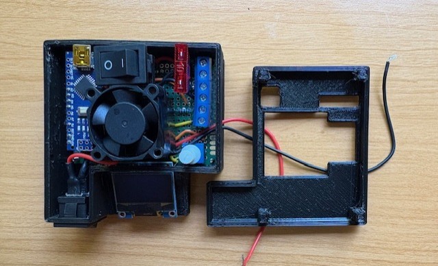
While building my DIY 3d printer, I've run into several roadblocks along the way. One of which being the temperature read and controlled output of the 3d printers heated bed. Currently, the main controls of my printer (for motor drivers, hotend, LCD display) are run on an arduino mega accompanied by a modified RAMPs 1.4 shield operating at 24 volts (marlin firmware). For whatever reason, after every attempt to drive the heated bed through RAMPs 1.4, my printer would run into several performance issues: - Inaccurate readings from bed thermistor - Bed continuously heating up, runaway temps well past desired temperature - Miscellaneous lapse in readings from hotend thermistor causing hotend temp runaways causing print failures (but only when bed was attached)
Whether it was the RAMPs 1.4 shield itself, or the bed not playing well with my current setup, I decided to build an additional system to read heated bed temps, set, and hold bed temps via PID Control.
In order to measure temps, the arduino must measure the voltage at the point past the thermistor and another "known" resistor (voltage-divider). The resistance of the thermistor embedded in my heated bed is approximately 10k ohms. A 10k ohm pull-down resistor is set up and an analog pin is set and gets fed back the voltage at the point past the thermistor + pull-down resistor see circuit diagram.
The Steinhart–Hart equation is used to calculate temperature from the resistance reading on the thermistor.
A modified PID control algorithm is used to balance temperatures around a setpoint, where setpoint is the desired temperature and is set via potentiometer.
The standard output range on the Arduino PWM pin allows for values between 0 - 255. For my purposes, this range in temperature (degrees fahrenheit) works fine, but if higher temps are required I'd recommend driving MOSFET gate by another means (analog pin, optocoupler, etc).
Arduino drives MOSFET by sending PWM-capped PID values to the MOSFET gate pin (protected by 330R resistor). MOSFET then controls the flow of current from the 24v external power supply to the heated bed, heating it up (Arduino and MOSFET share ground).
Warning: The values saved in main.cpp were consistently off by 3 degrees fahrenheit of the actual temperature measured by a thermometer I used as a control. A 3 degree fahrenheit error margin is acceptable for my purposes, but it's important to tune the Kp, Ki, and Kd values specific for your setup.
OLED display uses I2C protocol and serial communication is handled via the Adafruit_SSD1306 library to write relevant data to display.
Display data key:
Set: The current set temperature by potentiometer
Read: The current temperature read from thermistor
PiD: current PID value (capped between 0-255 for PWM)
Time: time elapsed in milliseconds
Streamline everything to run at 12 volts
Updates to 3d models
Kicad circuit design to fully milled PCB
| Qty | Value | Footprint | References |
|---|---|---|---|
| 2 | SW_SPST | Library:screw_mount | Switch1, Switch2 |
| 1 | 10K | Library:screw_mount | Resistor1 |
| 1 | 12v | Library:screw_mount | Power1 |
| 1 | 24v | Library:screw_mount | Power2 |
| 1 | 330R | Library:screw_mount | Resistor2 |
| 1 | Arduino_Nano_v3.x | Module:Arduino_Nano | A1 |
| 1 | Heated Bed | Library:screw_mount | R2 |
| 1 | IRF3205 | Package_TO_SOT_THT:TO-220-3_Vertical | MOSFET |
| 1 | R_Potentiometer | Library:arduino_kit_potentiometer | Potentiometer |
| 1 | Thermistor | Library:screw_mount | Thermistor1 |
| 1 | ~ | Library:OLED_display | OLED_display1 |
It measures 78 × 52 mm and has 2 copper layers, 1.6 mm thick.
12 parts, built around the IRF3205. The full list of its parts is on this page, with links to each part's symbol and footprint where PCBKit's library has them.
From the Morfeam/HeatedBed repository on GitHub, at the commit this page was made from: the board is kicad_files/heated_bed_controller.kicad_pcb and its schematic kicad_files/heated_bed_controller.kicad_sch. PCBKit opens the board in the browser, with nothing to install.
Its repository states no licence, so its author keeps all rights: ask Morfeam before reusing the design.
stancecoke/BionX_Minimal_Translator
Drive your BionX motor with a no-name battery and a Kunteng LCD-display without any further BionX-components


jayanta525/dual-h-bridge
Dual H-Bridge Controller with IRF3205 and IR2104 MOSFET Driver, and with ATMega328P-AU PWM Controller


ampnics/Project-10
Mater KiCad with Projects is a series of lectures in which we are learning PCB designing
