2 layers149 × 104 mm
 moonpolysoft/marker-lamp-controller
circuit and enclosure design for an aftermarket lamp controller for a 2023 f150 lightning
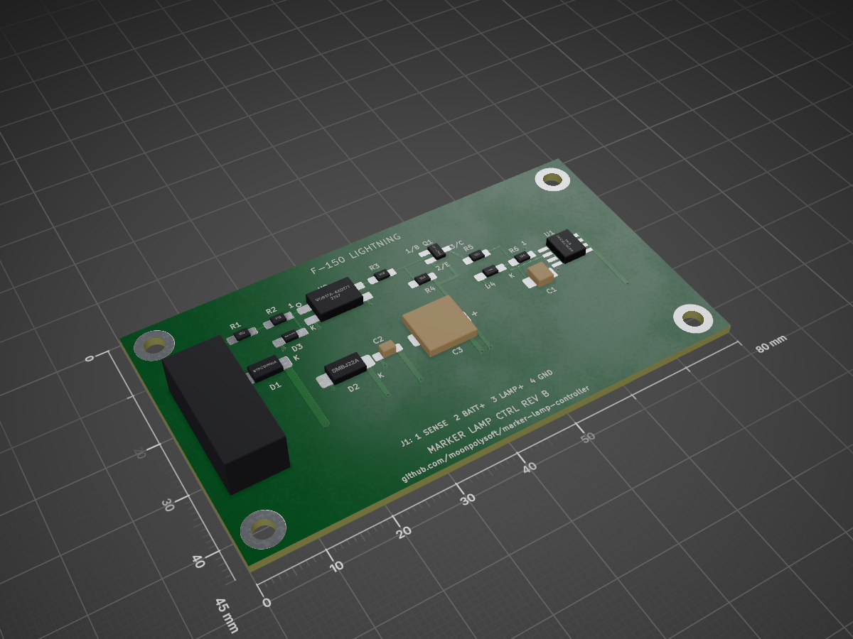
Marker lamp controller rev b is an open-source printed circuit board by moonpolysoft, from the moonpolysoft/marker-lamp-controller repository on GitHub, published under the CERN-OHL-S-2.0 licence. It is a 2-layer board of 80 × 45 mm with 21 parts on 11 nets, routed with 61 tracks and 16 vias.
It is built around the BSP762TXUMA1, VO617A-4X017T and 1N4148WS, with the BC807-40, BZT52C5V1 and SMBJ22A among its other parts. Its parts include 6 resistors, 4 diodes, 3 capacitors, 2 ICs and 1 transistor. It belongs with the lEDs and displays boards of this library.


This directory contains Revision A and Revision B of the two-layer marker-lamp controller. Revision B is the current fabrication design.
marker-lamp-controller.kicad_pcb — generated KiCad 10 PCB.marker-lamp-controller-rev-b.kicad_pcb — corrected Revision B PCB.generate_pcb.py — deterministic PCB generator using KiCad's pcbnew
Python module.circuit-netlist.md — readable authoritative circuit connectivity.revision-b-notes.md — corrections found while assembling Revision A that
must be incorporated before the next board order.BOM.csv — orderable manufacturer and DigiKey part numbers.drc-report.txt — KiCad board DRC result.fabrication/ — OSH Park Gerbers and separate plated/non-plated drills.fabrication-rev-b/ — Revision B OSH Park Gerbers, drills, and upload ZIP.board-render.png — top-side board preview (custom hand-solder footprints
do not carry 3D body models).board-render-rev-b.png — Revision B top-side board preview.Revision B includes top-side reference designators, diode cathode markings, C3 polarity, U1/U2 pin-1 cues, Q1 lead labels, the complete J1 pinout, and the project source URL to support hand assembly and design-source identification.
The PCB generator and circuit-netlist.md are authoritative for Revision B.
Board header:
TBP01R1-508-04BEMating pluggable terminal connector:
TBP01P1-508-04BEPinout:
SENSE — driver-side rear parking output, C4483 cavity 10,
violet/green.BATT+ — separately fused 12 V feed; use a 2 A fuse.LAMP+ — switched positive output to the 0.25 A grille LEDs.GND — chassis ground and grille LED return.These values exceed the OSH Park two-layer minima of 0.1524 mm trace/spacing, 0.127 mm annular ring, and 0.254 mm minimum drill.
The BOM was checked against DigiKey stock on 2026-07-24. Stock changes continuously, so verify it again before ordering.
python3 generate_pcb.pyRun from this directory or from the project root using the full relative path.
Generate the top-side repository preview from the project root with:
kicad-cli pcb render --side top --quality basic --background opaque \
  --width 1600 --height 900 --zoom 1.15 \
  -o hardware/kicad/board-render-rev-b.png \
  hardware/kicad/marker-lamp-controller-rev-b.kicad_pcb
The custom hand-solder footprints do not include 3D component-body models, so the render intentionally shows the bare board, pads, and assembly silkscreen.
An assembled Revision B board has been bench tested, installed, and verified working in the vehicle with the intended 0.25 A marker-lamp load. It remains an engineering prototype; independent builders should bench test every assembly and characterize turn-on/off behavior, reverse polarity, output short protection, thermal behavior, and vehicle sleep current before permanent installation.
KiCad 10 DRC reports zero violations, zero unconnected pads, and zero footprint errors for Revision B. This verifies the artwork rules and connectivity, not vehicle behavior.
| Qty | Value | Footprint | References |
|---|---|---|---|
| 4 | M3 | H1, H2, H3, H4 | |
| 2 | 100k | R4, R6 | |
| 2 | 10k | R3, R5 | |
| 2 | 1k | R1, R2 | |
| 1 | 100n 50V | C2 | |
| 1 | 10u 25V | C1 | |
| 1 | 1N4148WS | D3 | |
| 1 | 47u 50V | C3 | |
| 1 | BC807-40 | Q1 | |
| 1 | BSP762TXUMA1 | U1 | |
| 1 | BZT52C5V1 | D4 | |
| 1 | SMBJ22A | D2 | |
| 1 | STPS2H100A | D1 | |
| 1 | TBP01R1-508-04BE | J1 | |
| 1 | VO617A-4X017T | U2 |
It measures 80 × 45 mm and has 2 copper layers, 1.6 mm thick.
21 parts, built around the BSP762TXUMA1, VO617A-4X017T, 1N4148WS and BC807-40. The full list of its parts is on this page, with links to each part's symbol and footprint where PCBKit's library has them.
From the moonpolysoft/marker-lamp-controller repository on GitHub, at the commit this page was made from: the board is hardware/kicad/marker-lamp-controller-rev-b.kicad_pcb. PCBKit opens the board in the browser, with nothing to install.
Its repository publishes it under the CERN-OHL-S-2.0 licence: you may reuse it on that licence's terms (keep the author's notice, and for a copyleft licence share your changes alike).


hharte/rpi-simplex-clock-hat
Raspberry Pi Hat to control a Simplex synchronous clock.

borzeman/PzbElectronics
Репозиторий для поддержки версионирования при разработке плат для киоска.

DD1SB/ARDF-TX
Date: 2026-10-15. Engineering review only; unbuilt and unenergized. Open RF80.kicadpro, schematic and native PCB in KiCad10.0.6. Three primary PCBs and the separate VHF true-AM design are unchanged.


barkinvar/sugerCANe
A compact interface for three NPN, PNP or logic sensors on an FRC robot. Each port has a removable 5 V / 12 V power jumper; input type is configured in software.