

2 layers185 × 60 mm
PI keys
MonkeyCodeMen/ULC-Pico-C-Code
ULC - Pico universal light controller with Rasperry Pico
33 parts1MIT
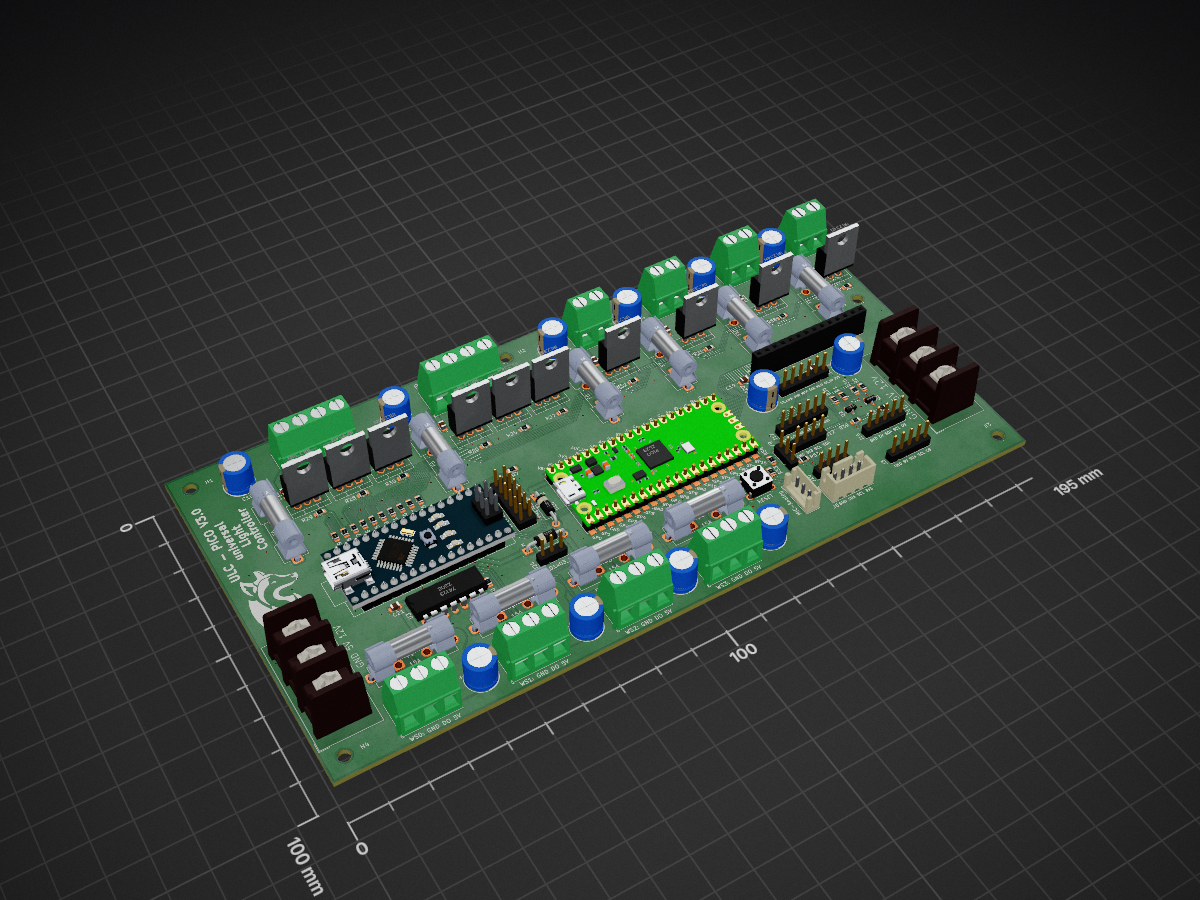
 MonkeyCodeMen/ULC-Pico-C-Code1
ULC - Pico universal light controller with Rasperry Pico
Pico.Light controller is an open-source printed circuit board by MonkeyCodeMen, from the MonkeyCodeMen/ULC-Pico-C-Code repository on GitHub, published under the MIT licence. It is a 2-layer board of 195 × 100 mm with 117 parts on 107 nets, routed with 971 tracks and 162 vias.
It is built around the IRLZ34N and BSS138. Its parts include 35 resistors, 25 capacitors, 20 connectors, 12 transistors and 10 fuses. It belongs with the lEDs and displays boards and the RP2040 and AVR (ATmega, ATtiny) boards of this library.
All started with the purchasing of Raspberry Pico RP2040 in 2023.
a fascinating dual core processor for less than 5€ (gosh do you know what we have paied for Z80 or 68K when I started with µController) .. congratulation to the raspberry foundation good job
The Arduino IDE beacomes to small for this number files so I changed to Visual Studio Code with PlatformIO .. fascinating all for free .. and the integration of RP2040 from maxgerhardt outstanding .. Thanks a lot
I tried several other things like:


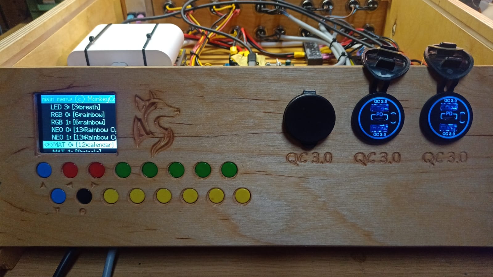
.. I think I show you a picture of the current state:
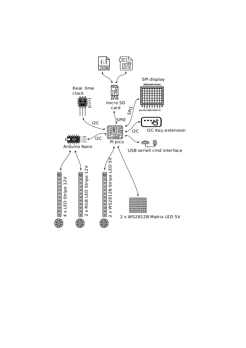
I just want to explore how it works and it lead to this .. but it will not be the end, it just reached a state where I decided to make it public to give something back to the community, in the hope it may be usefull for somebody. And don’t forget: always stay curious and persistent. The best way to learn is through mistakes. But only those who try something new and unfamiliar can make mistakes to learn from. Every day without learning something is a lost day.
So, search behind every tree and under very stone for the three-headed monkey, and if you need a boat, just ask for Stan.
The project keeps growing and growing .. I needed a PCB .. I found KiCad : @KiCad Team .. a professional layout tool for free .. great work ...
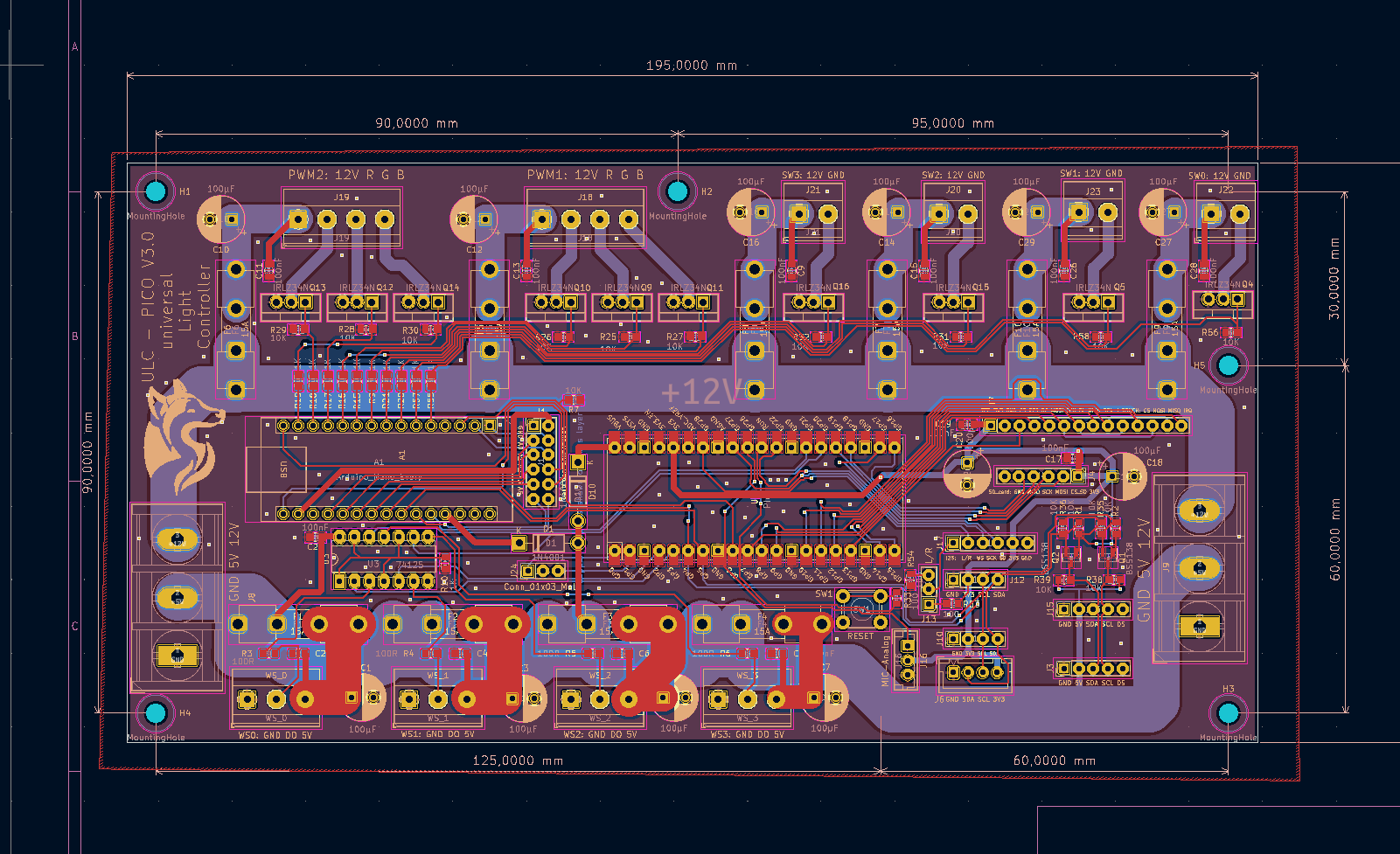
there were now a lot of components so I needed a hosuing .. you will not belief there is a free M-CAD tool : freecad
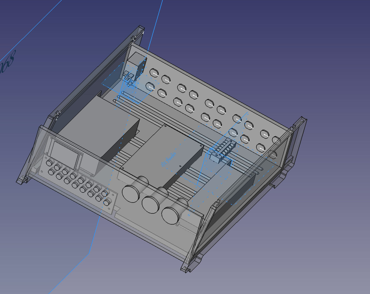
I build all in wood an milled it on my MP CNC (a nice free project for CNC machine please look for it) And this is the final result:
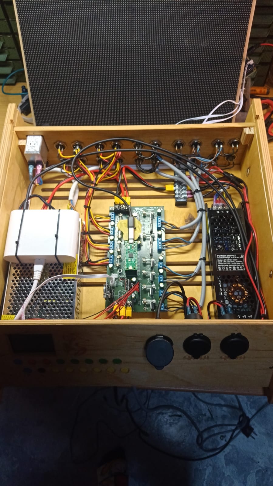
mainly it control several types of LED (a lot of them)
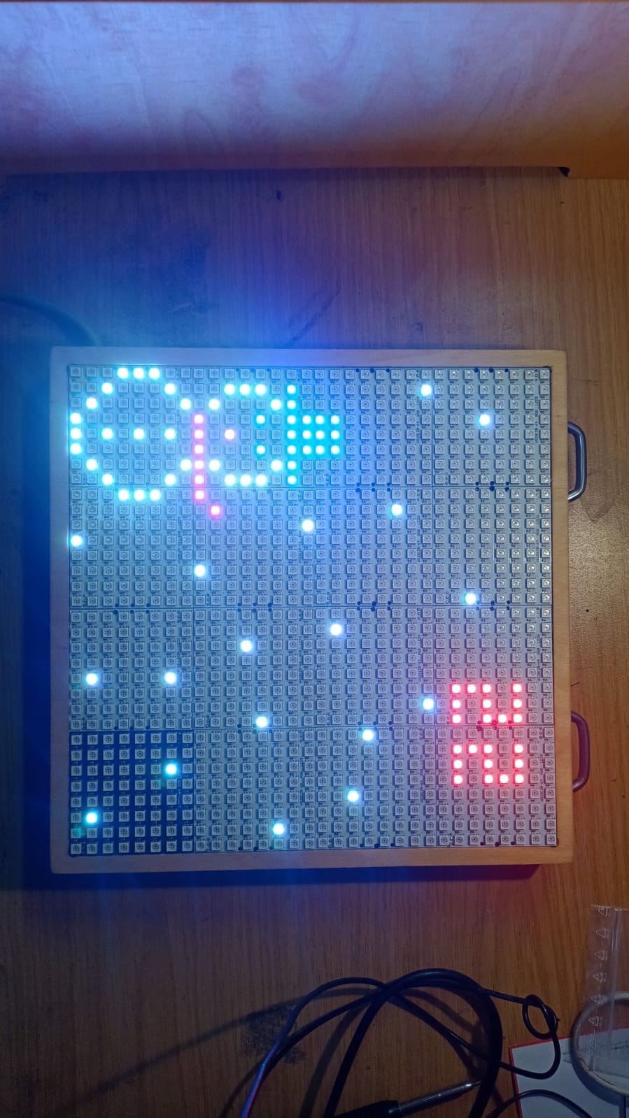
one example a advent calendar for nurds:
some more details:
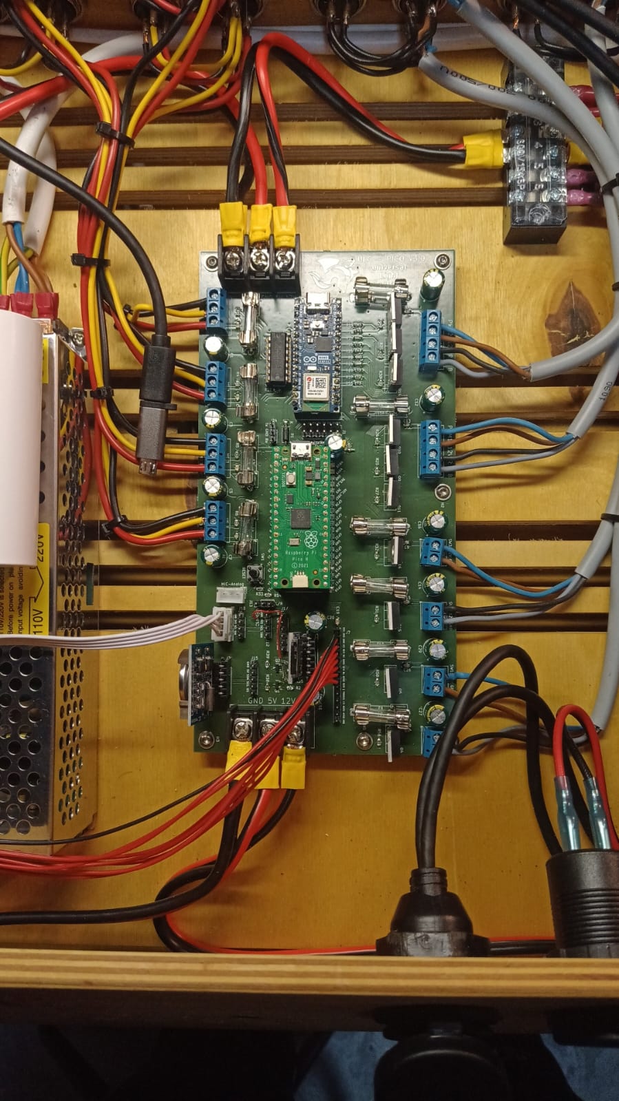
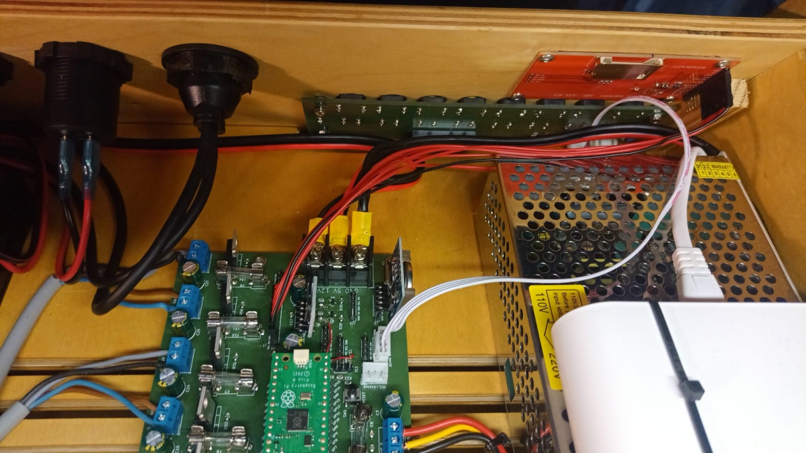
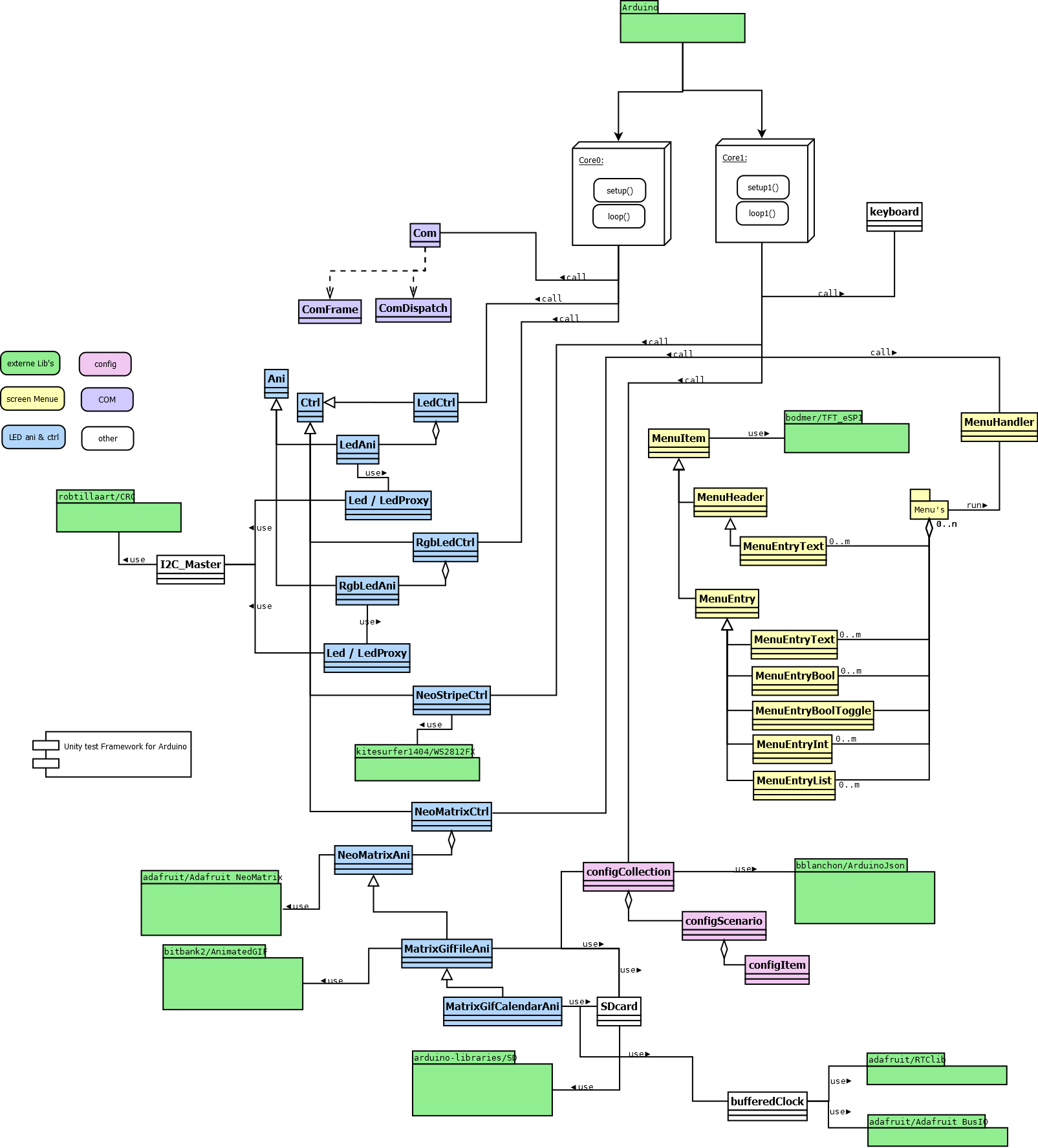
I staied with the Arduino loop concept and designed the most classes in this manner. This is not suitable for hard real time rqeuirement, but it is easy and with the performance of the two cores of the RP2040 it is amazing what is possible.
But from my experience I use during one loop run a fixed time (now). I freeze this time at the begin of the loop and pass it than to every module that is been called in this loop.
In addition to that I have a favor for the rough concept of state-machine with init run etc...
For more details please refer the comment of the individual classes.
ToDo description to :
Below is a list of the libraries or frameworks required for the project to run. Make sure to install them before proceeding.
Many thanks to all the amazing developers of these libraries. Based on this foundation, it is possible to create larger projects like this one with a moderate amount of time. This enables significantly more functionality than would have been achievable by a single person alone.
All Lib's will be installed by PlatformIO based on ini file .. perfect .. @PlatforIO team: outstanding job, i know several professional tools from automobile industry that can not do this !!!!
https://github.com/maxgerhardt/platform-raspberrypi.git
@all LIB authors .. great job, please keep up this good work
git clone https://github.com/MonkeyCodeMen/ULC-Pico-C-Code.gitToDo
ToDo
The MIT License (MIT)
Copyright (c) 2024 MonkeyCodeMen@GitHub
Permission is hereby granted, free of charge, to any person obtaining a copy of this software and associated documentation files (the "Software"), to deal in the Software without restriction, including without limitation the rights to use, copy, modify, merge, publish, distribute, sublicense, and/or sell copies of the Software, and to permit persons to whom the Software is furnished to do so, subject to the following conditions:
The above copyright notice and this permission notice shall be included in all copies or substantial portions of the Software.
THE SOFTWARE IS PROVIDED "AS IS", WITHOUT WARRANTY OF ANY KIND, EXPRESS OR IMPLIED, INCLUDING BUT NOT LIMITED TO THE WARRANTIES OF MERCHANTABILITY, FITNESS FOR A PARTICULAR PURPOSE AND NONINFRINGEMENT. IN NO EVENT SHALL THE AUTHORS OR COPYRIGHT HOLDERS BE LIABLE FOR ANY CLAIM, DAMAGES OR OTHER LIABILITY, WHETHER IN AN ACTION OF CONTRACT, TORT OR OTHERWISE, ARISING FROM, OUT OF OR IN CONNECTION WITH THE SOFTWARE OR THE USE OR OTHER DEALINGS IN THE SOFTWARE.
have fun !!
| Qty | Value | Footprint | References |
|---|---|---|---|
| 17 | 10K | Resistor_SMD:R_0805_2012Metric_Pad1.20x1.40mm_HandSolder | R1, R2, R25, R26, R27, R28, R29, R30, R31, R32, R35, R36, R38, R39, R56, R58 +1 |
| 13 | 100nF | Capacitor_SMD:C_0805_2012Metric_Pad1.18x1.45mm_HandSolder | C2, C4, C6, C8, C9, C11, C13, C15, C17, C19, C21, C26, C28 |
| 12 | 100µF | Capacitor_THT:CP_Radial_D8.0mm_P3.80mm | C1, C3, C5, C7, C10, C12, C14, C16, C18, C20, C27, C29 |
| 11 | 1K | Resistor_SMD:R_0805_2012Metric_Pad1.20x1.40mm_HandSolder | R9, R10, R15, R16, R17, R18, R19, R20, R21, R55, R57 |
| 10 | 15A | Fuse:Fuseholder_Clip-5x20mm_Eaton_1A5601-01_Inline_P20.80x6.76mm_D1.70mm_Horizontal | F1, F2, F3, F4, F5, F6, F7, F8, F9, F10 |
| 10 | IRLZ34N | Package_TO_SOT_THT:TO-220-3_Vertical | Q4, Q5, Q9, Q10, Q11, Q12, Q13, Q14, Q15, Q16 |
| 5 | MountingHole | MountingHole:MountingHole_3.2mm_M3 | H1, H2, H3, H4, H5 |
| 4 | 100R | Resistor_SMD:R_0805_2012Metric_Pad1.20x1.40mm_HandSolder | R3, R4, R5, R6 |
| 3 | 100 | Resistor_SMD:R_0805_2012Metric_Pad1.20x1.40mm_HandSolder | R33, R53, R54 |
| 2 | 1N4001 | Diode_THT:D_DO-41_SOD81_P10.16mm_Horizontal | D1, D10 |
| 2 | BSS138 | Package_TO_SOT_SMD:SOT-23 | Q1, Q2 |
| 2 | GND 3V3 SCL SDA | Connector_PinHeader_2.54mm:PinHeader_1x04_P2.54mm_Vertical | J10, J12 |
| 2 | GND 5V 12V | TerminalBlock_Dinkle:TerminalBlock_Dinkle_DT-55-B01X-03_P10.00mm | J8, J9 |
| 2 | GND 5V SDA SCL DS | Connector_PinHeader_2.54mm:PinHeader_1x05_P2.54mm_Vertical | J3, J15 |
| 1 | 74125 | Package_DIP:DIP-14_W7.62mm_LongPads | U3 |
| 1 | Arduino_Nano_Every | Module:Arduino_Nano | A1 |
| 1 | Conn_01x03_Male | Connector_PinHeader_2.54mm:PinHeader_1x03_P2.54mm_Vertical | J24 |
| 1 | Conn_02x06_Odd_Even | Connector_PinHeader_2.54mm:PinHeader_2x06_P2.54mm_Vertical | J1 |
| 1 | GND SDA SCL 3V3 | Connector_JST:JST_XH_B4B-XH-A_1x04_P2.50mm_Vertical | J6 |
| 1 | I2S: L/R WS SCK SD 3V3 GND | Connector_PinHeader_2.54mm:PinHeader_1x06_P2.54mm_Vertical | J17 |
| 1 | L/R | Connector_PinHeader_2.54mm:PinHeader_1x03_P2.54mm_Vertical | J13 |
| 1 | MIC-Analog | Connector_JST:JST_EH_B3B-EH-A_1x03_P2.50mm_Vertical | J16 |
| 1 | PWM1: 12V R G B | TerminalBlock_Phoenix:TerminalBlock_Phoenix_MKDS-1,5-4_1x04_P5.00mm_Horizontal | J18 |
| 1 | PWM2: 12V R G B | TerminalBlock_Phoenix:TerminalBlock_Phoenix_MKDS-1,5-4_1x04_P5.00mm_Horizontal | J19 |
| 1 | Pico | Modules_User:RPi_Pico_SMD_TH_Kopie | U1 |
| 1 | RESET | Button_Switch_THT:SW_PUSH_6mm | SW1 |
| 1 | SD_card: GND MISO SCK MOSI CS_SD 3V3 | Connector_PinHeader_2.54mm:PinHeader_1x06_P2.54mm_Vertical | J4 |
| 1 | SW0: 12V GND | TerminalBlock_Phoenix:TerminalBlock_Phoenix_MKDS-1,5-2_1x02_P5.00mm_Horizontal | J22 |
| 1 | SW1: 12V GND | TerminalBlock_Phoenix:TerminalBlock_Phoenix_MKDS-1,5-2_1x02_P5.00mm_Horizontal | J23 |
| 1 | SW2: 12V GND | TerminalBlock_Phoenix:TerminalBlock_Phoenix_MKDS-1,5-2_1x02_P5.00mm_Horizontal | J20 |
| 1 | SW3: 12V GND | TerminalBlock_Phoenix:TerminalBlock_Phoenix_MKDS-1,5-2_1x02_P5.00mm_Horizontal | J21 |
| 1 | TFT: 3V3 GND CS RES DC MOSI SCK BL MISO SCK | TOUCH: CS MOSI MISO IRQ | Connector_PinSocket_2.54mm:PinSocket_1x14_P2.54mm_Vertical | J7 |
| 1 | WS0: GND DO 5V | TerminalBlock_Phoenix:TerminalBlock_Phoenix_MKDS-1,5-3_1x03_P5.00mm_Horizontal | WS_0 |
| 1 | WS1: GND DO 5V | TerminalBlock_Phoenix:TerminalBlock_Phoenix_MKDS-1,5-3_1x03_P5.00mm_Horizontal | WS_1 |
| 1 | WS2: GND DO 5V | TerminalBlock_Phoenix:TerminalBlock_Phoenix_MKDS-1,5-3_1x03_P5.00mm_Horizontal | WS_2 |
| 1 | WS3: GND DO 5V | TerminalBlock_Phoenix:TerminalBlock_Phoenix_MKDS-1,5-3_1x03_P5.00mm_Horizontal | WS_3 |
It measures 195 × 100 mm and has 2 copper layers, 1.6 mm thick.
117 parts, built around the IRLZ34N and BSS138. The full list of its parts is on this page, with links to each part's symbol and footprint where PCBKit's library has them.
From the MonkeyCodeMen/ULC-Pico-C-Code repository on GitHub, at the commit this page was made from: the board is PCB/Pico.Light-controller/Pico.Light-controller.kicad_pcb and its schematic PCB/PI-keys/PI-keys.kicad_sch. PCBKit opens the board in the browser, with nothing to install.
Its repository publishes it under the MIT licence: you may reuse it on that licence's terms (keep the author's notice, and for a copyleft licence share your changes alike).
MonkeyCodeMen/ULC-Pico-C-Code
ULC - Pico universal light controller with Rasperry Pico


Hans-Beerman/Deurnode_ESP32-PoE
KiCad design Deurnode for the MakerSpace Leiden, based on the Olimex ESP32-PoE

3D-Printing-for-Microfluidics/3D_printer_control
2nd generation 3D printer control software

DavidJ-Saving-Time/watch-cleaner
So this is a very rough draft of code designed to run on an esp32 to control a watch cleaning machine see this YouTube video https://youtu.be/Opr75n8DbYY I'll be adding to this and making it easier for people to use.

destroyer796/3DWelder
An overbuilt 3D pen that will use a chc pro hotend and custom dc extruder powered by a power tool battery

grillbaer/solar-power-supply
Solar power harvesting for micro controller projects with li-Ion battery and highly efficient charge controller

volw/wifiOiler
Automatic, distance depending chain oiler for motorbikes with track recording (GPS).

aidtopia/spider_dropper
Mechanism to "drop" a spider (or other lightweight prop) for Halloween fun