2 layers49.5 × 49.7 mm
AudioPowerBoard
LEAT-EDGE/ambient-pcb-audiopower
Audio capture and energy management daughterboard PCB for the Ambient project.
121 partsCERN-OHL-P-2.0

 monash-human-power/power-meter
Power meter designed as part of Oscar Varney and Jotham Gates' FYP in 2024
Power meter pcb is an open-source printed circuit board by monash-human-power, from the monash-human-power/power-meter repository on GitHub, published under the MIT licence. It is a 4-layer board of 23 × 51.5 mm with 64 parts on 76 nets, routed with 637 tracks and 87 vias.
It is built around the ESP32-S3-MINI-1-N8, ADS1232IPW and P3T1755DP, with the TPD3E001DRLR, AS2302 and CLX6F-FKC-CNP1ST1E1BB7D3D3 among its other parts. Its parts include 19 resistors, 15 capacitors, 7 connectors, 5 ICs and 3 diodes. It belongs with the sensors and measurement boards and the ESP32 boards of this library.


Oscar Varney and Jotham Gates, 2024
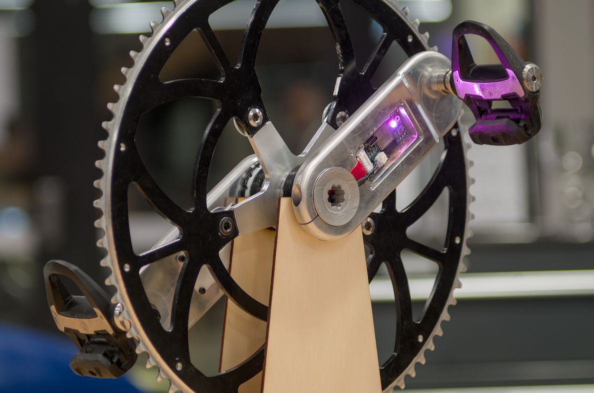
This is the code repository for a Final Year Project (FYP) to develop a crankset and power meter for Human Powered Vehicles (HPVs).
The schematic and PCB layout were completed using KiCAD 9. The design files are in the power-meter-pcb folder.
The firmware is written to use the Arduino environment of Platform IO and is located in the power-meter-code directory.
Install the following libraries, either by using the Arduino library manager or going to their GitHub repository and cloning them.
A bash script has been written to update the dates on all modified or staged files (not including untracked files). To perform this operation, run:
./tools/update_date.shAnother script is included to update the version info on all files and definitions for the code. The files and elements updated include:
@version tags in the code directory.VERSION definition in defines.h.Doxyfile.As an example:
./tools/update_version.sh 1.2.3This needs to be modified to work with the platform IO structure. Copy the
pre-commitfile into.git/hooks/pre-commit. This will check the date of code files and make sure they are up to date.
Documentation can be automatically generated using Doxygen by running doxygen from the root folder of the repository. You might need to install doxygen and graphviz first. The output will be placed in the docs folder. GitHub actions may be set up later down the track to automatically generate and deploy to GitHub pages on commit- however that would require a public repository and documentation.
To generate a massive appendix for the report, run ./tools/generate_refman.sh
The output file will be refman.pdf.
Scripts for testing the board hardware and easing development of certain sections can be found in the scripts-testing directory. This includes python scripts used to log data over MQTT and plot it.
| Qty | Value | Footprint | References |
|---|---|---|---|
| 7 | 22u | Capacitor_SMD:C_0603_1608Metric_Pad1.08x0.95mm_HandSolder | C3, C4, C5, C6, C7, C14, C15 |
| 6 | 0.1u | Capacitor_SMD:C_0603_1608Metric_Pad1.08x0.95mm_HandSolder | C8, C9, C10, C11, C12, C13 |
| 4 | 47 | Resistor_SMD:R_0603_1608Metric_Pad0.98x0.95mm_HandSolder | R10, R14, R15, R16 |
| 4 | 5.1k | Resistor_SMD:R_0603_1608Metric_Pad0.98x0.95mm_HandSolder | R6, R7, R8, R9 |
| 3 | 150 | Resistor_SMD:R_0603_1608Metric_Pad0.98x0.95mm_HandSolder | R3, R4, R19 |
| 3 | MountingHole | MountingHole:MountingHole_2.2mm_M2 | H1, H2, H3 |
| 2 | 10k | Resistor_SMD:R_0603_1608Metric_Pad0.98x0.95mm_HandSolder | R1, R2 |
| 2 | 1M | Resistor_SMD:R_0603_1608Metric_Pad0.98x0.95mm_HandSolder | R11, R12 |
| 2 | 1u | Capacitor_SMD:C_0603_1608Metric_Pad1.08x0.95mm_HandSolder | C1, C2 |
| 1 | 100k | Resistor_SMD:R_0603_1608Metric_Pad0.98x0.95mm_HandSolder | R18 |
| 1 | 320 | Resistor_SMD:R_0603_1608Metric_Pad0.98x0.95mm_HandSolder | R5 |
| 1 | 453k | Resistor_SMD:R_0603_1608Metric_Pad0.98x0.95mm_HandSolder | R17 |
| 1 | 470 | Resistor_SMD:R_0603_1608Metric_Pad0.98x0.95mm_HandSolder | R13 |
| 1 | 470n | Inductor_SMD:L_Vishay_IHLP-1212 | L1 |
| 1 | 5V | TestPoint:TestPoint_Pad_1.5x1.5mm | TP1 |
| 1 | ADS1232IPW | Package_SO:TSSOP-24_4.4x7.8mm_P0.65mm | U5 |
| 1 | AS2302 | Package_TO_SOT_SMD:TSOT-23 | Q1 |
| 1 | Address select | Jumper:SolderJumper-3_P1.3mm_Open_RoundedPad1.0x1.5mm | JP3 |
| 1 | BOOT | Button_Switch_SMD:SW_Push_1P1T_NO_CK_KMR2 | SW2 |
| 1 | Battery | Connector_JST:JST_PH_S2B-PH-K_1x02_P2.00mm_Horizontal | J4 |
| 1 | CLX6F-FKC-CNP1ST1E1BB7D3D3 | RGB_LED_CLX6F-FKC-CNP1ST1E1BB7D3D3:PLCC6_3.4X3.4_CRW-M | D1 |
| 1 | Crank interconnect | Connector_JST:JST_PH_S8B-PH-K_1x08_P2.00mm_Horizontal | J1 |
| 1 | DOUT connect | Jumper:SolderJumper-2_P1.3mm_Open_RoundedPad1.0x1.5mm | JP2 |
| 1 | Debug | Connector_PinHeader_2.54mm:PinHeader_1x05_P2.54mm_Vertical | J2 |
| 1 | EN | Button_Switch_SMD:SW_Push_1P1T_NO_CK_KMR2 | SW1 |
| 1 | ESP32-S3-MINI-1 | RF_Module:ESP32-S2-MINI-1 | U1 |
| 1 | ICM-42670-P | ICM-42670-P_AccelGyro:XDCR_ICM-42670-P | MT1 |
| 1 | LED | LED_SMD:LED_0603_1608Metric_Pad1.05x0.95mm_HandSolder | D3 |
| 1 | MH2029-300Y | Inductor_SMD:L_0805_2012Metric | FB1 |
| 1 | NetTie_2 | NetTie:NetTie-2_SMD_Pad0.5mm | NT1 |
| 1 | P3T1755 | Package_SO:TSSOP-8_3x3mm_P0.65mm | U2 |
| 1 | PMEG6030ELPX | Diode_SMD:D_SOD-128 | D4 |
| 1 | SCLK connect | Jumper:SolderJumper-2_P1.3mm_Open_RoundedPad1.0x1.5mm | JP1 |
| 1 | SMD1206B200TF | Fuse:Fuse_1206_3216Metric_Pad1.42x1.75mm_HandSolder | F1 |
| 1 | Side A | Connector_PinHeader_2.54mm:PinHeader_1x04_P2.54mm_Vertical | J6 |
| 1 | Side B | Connector_PinHeader_2.54mm:PinHeader_1x04_P2.54mm_Vertical | J7 |
| 1 | Spare GPIO pins | Connector_PinHeader_2.00mm:PinHeader_1x06_P2.00mm_Vertical | J3 |
| 1 | TPD3E001DRLR | Package_TO_SOT_SMD:SOT-553 | U4 |
| 1 | TPS61023DRLR | TPS61023DRLR:DRL0006A | U3 |
| 1 | USB4120-03-C_REVA | USB4120:GCT_USB4120-03-C_REVA | J5 |
LEAT-EDGE/ambient-pcb-audiopower
Audio capture and energy management daughterboard PCB for the Ambient project.

Fominsky/HIGH-SPEED-USB-ISOLATOR
High-speed USB isolator with external power based on ADuM3165/ADuM3166

second-string/capacitive-touch-button-board-prototype
Protoype hardware and firmware for evaluating different designs of capacitive touch buttons and reverse-mount LEDs


easyhive/easyhive_kicad
Kicad files for PCB production of easyhive boards which are used in easyhive hive scale.
It measures 23 × 51.5 mm and has 4 copper layers, 1.6 mm thick.
64 parts, built around the ESP32-S3-MINI-1-N8, ADS1232IPW, P3T1755DP and TPD3E001DRLR. The full list of its parts is on this page, with links to each part's symbol and footprint where PCBKit's library has them.
From the monash-human-power/power-meter repository on GitHub, at the commit this page was made from: the board is power-meter-pcb/power-meter-pcb.kicad_pcb and its schematic power-meter-pcb/accelerometer.kicad_sch. PCBKit opens the board in the browser, with nothing to install.
Its repository publishes it under the MIT licence: you may reuse it on that licence's terms (keep the author's notice, and for a copyleft licence share your changes alike).