


2 layers100 × 64.7 mm

 MohammedHarbe/metal-monster1
Griffen by Vanguards. An engineering journey since 2023. Mechanical fabrication, custom electronics, and ESP-NOW control.
Reciever metal monster is an open-source printed circuit board by MohammedHarbe, from the MohammedHarbe/metal-monster repository on GitHub. It is a 2-layer board of 98.4 × 71.7 mm with 17 parts on 44 nets, routed with 80 tracks and 8 vias.
It is built around the BC338. Its parts include 5 connectors, 3 resistors, 2 diodes, 2 fuses and 1 transistor.

Griffen by Vanguards. An engineering journey since 2023.
Mechanical fabrication, custom electronics, and ESP-NOW control.
Mechanical · Firmware · Electrical · Our story · Watch the first run
We are Vanguards, and we have been working on Griffen since 2023: a manually controlled robot built for robot-versus-robot competition. Two wheelchair motors move the base, while a starter motor powers its metal spinner. A handheld remote communicates with an onboard ESP32 DevKitC V4 over ESP-NOW.
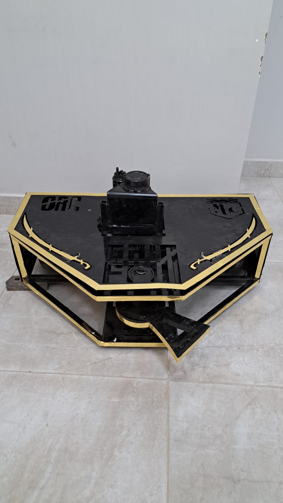 The painted robot | 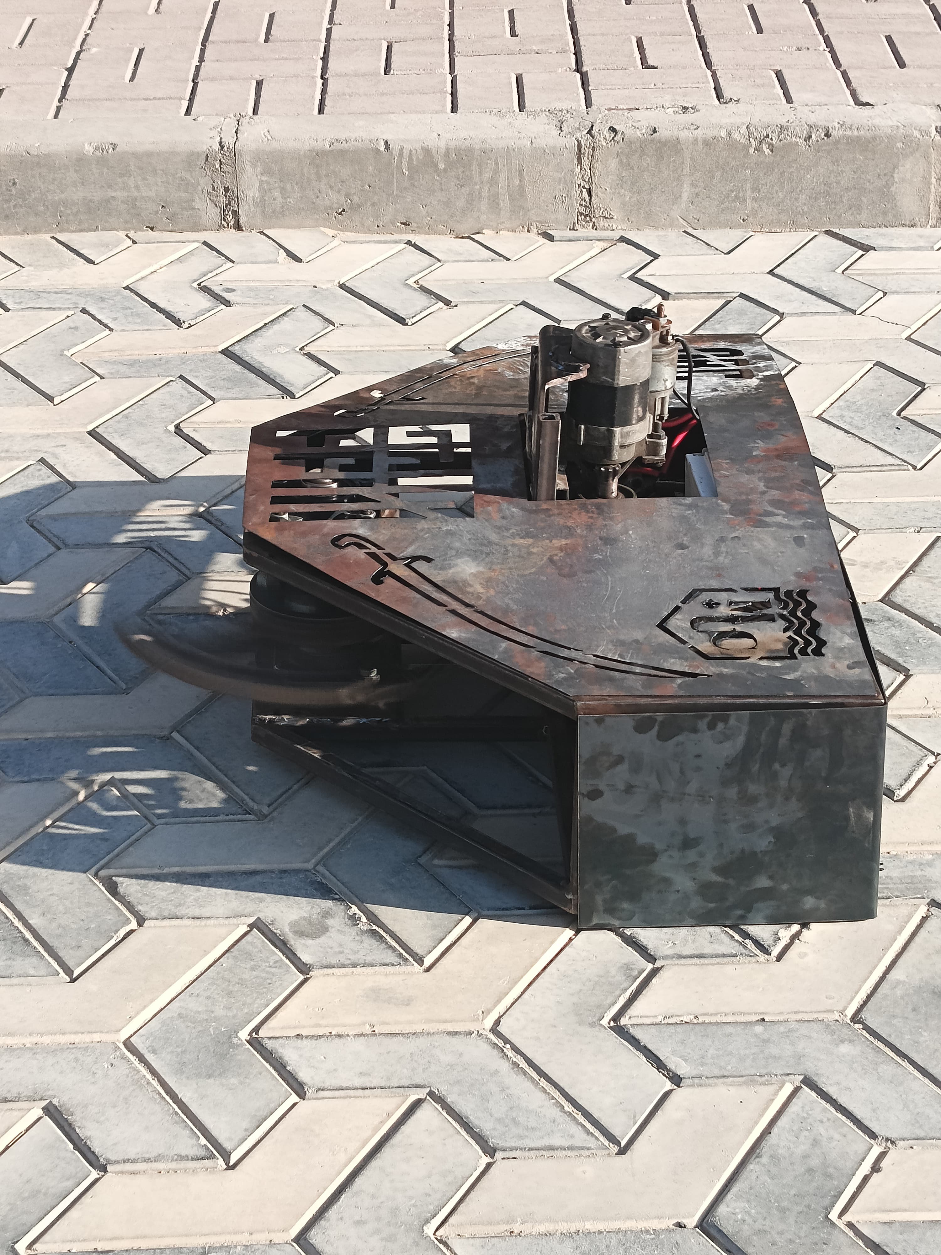 Before paint and later modifications |
▶ Watch or download our first integrated-operation video
A milestone identified by the team: the first time the robot worked together as a complete system.
The repository retains its original metal-monster name; Griffen is the robot and Vanguards is the team.
Download the supplied PCB logo DXF.
| Area | What you will find | Availability |
|---|---|---|
| Mechanical | Robot photos, motor references, and remote PCB CAD | Remote CAD included · chassis CAD to come |
| Firmware | Separate ESP-NOW remote and receiver sketches, setup notes, and known issues | Source included |
| Robot receiver | KiCad project, schematic, PCB, Gerbers, drill files, and renders | Design package included |
| Handheld remote | KiCad review package, PCB models, Gerbers, schematic PDFs, and renders | Design packages included |
| Project history | Early electronics, team photo, and first-operation video | Media included |
| HANDHELD REMOTE Manual inputs → ESP-NOW commands | ONBOARD RECEIVER ESP-NOW commands → motor and relay control |
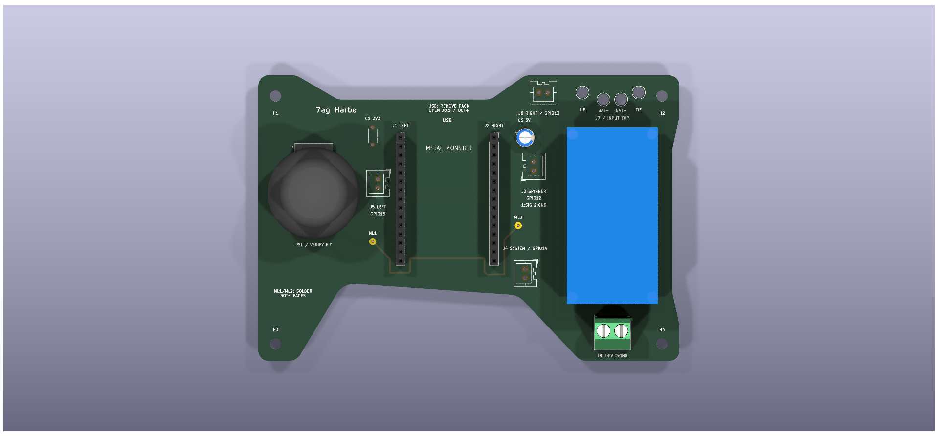 | 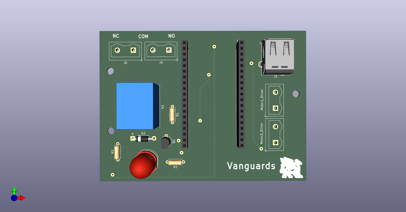 |
| The handheld remote reads joystick and switch inputs. Its supplied KiCad review package, mechanical exports, Gerbers, PDFs, and renders are now included. | The supplied custom PCB hosts the ESP32 DevKitC V4 and interfaces with the drive controller and spinner relay. |
| Drive system | Spinner system | |
|---|---|---|
| Motor | Two wheelchair motors | Starter motor driving a metal spinner |
| Control | MDD20A motor driver | BC338 transistor stage and relay |
| Battery | 24 V · 20 Ah lithium-ion | 11.1 V · 3S · 10.4 Ah LiPo |
| Reference | Drive battery | Battery listing |
The receiver uses an ESP32 DevKitC V4. Its spinner GPIO drives a 5 V relay coil through the BC338 interface; the relay contacts switch starter-motor power directly. The coil supply and motor supply are separate specifications.
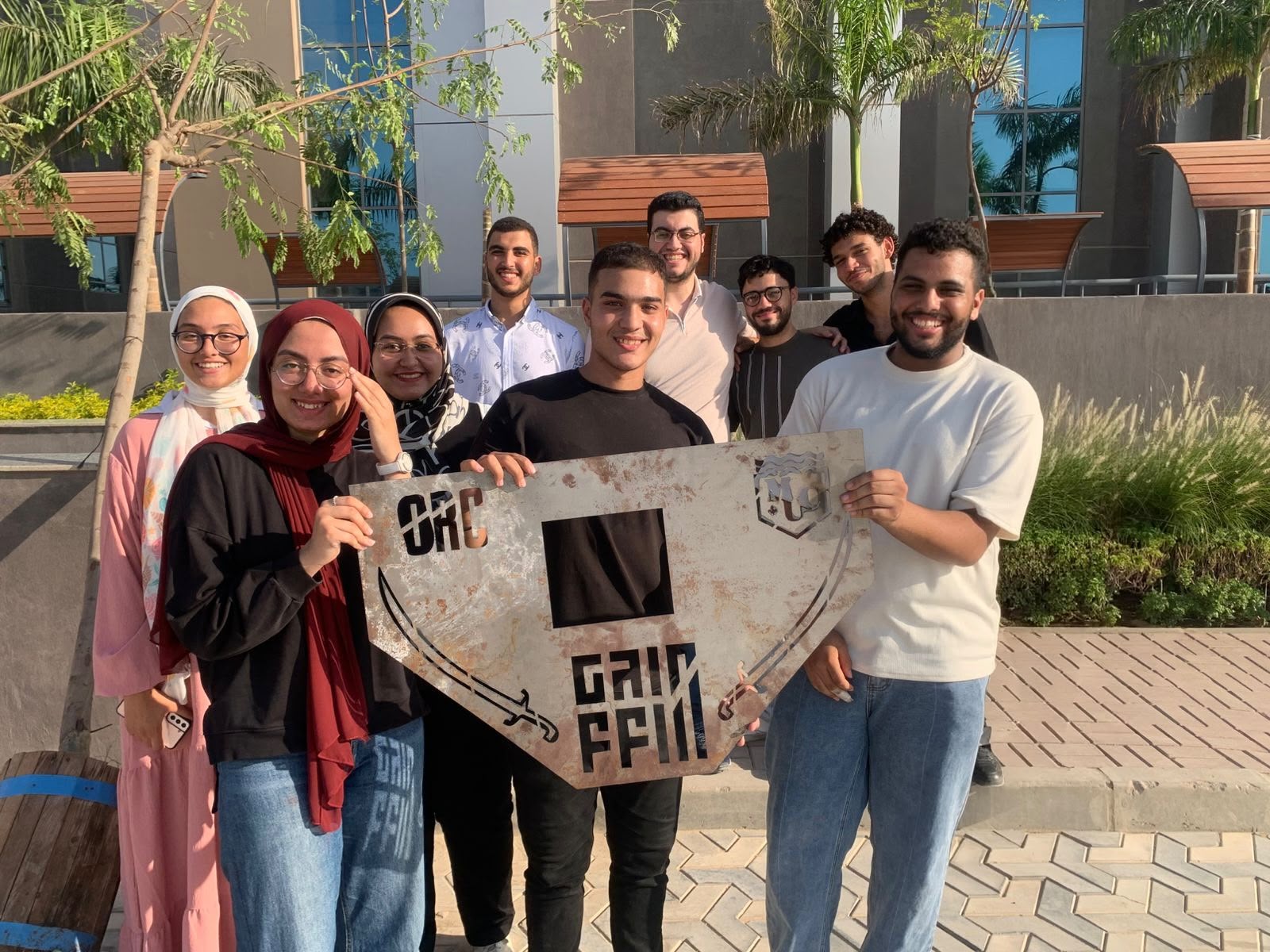
From the early receiver and handheld remote to the assembled robot, this repository brings our work into one place. The project history records those stages without assigning unconfirmed dates to individual milestones.
metal-monster/
├── mechanical/             Robot references and remote PCB CAD
├── firmware/
│   ├── esp-now/
│   │   ├── trans/          Handheld remote sketch
│   │   └── reciver/        Robot receiver sketch
│   └── legacy/             Original unused SBUS sketch
├── electrical/
│   ├── receiver/
│   │   ├── source/         Editable KiCad files
│   │   ├── manufacturing/  Gerbers, drills, and original archive
│   │   ├── schematics/     Schematic PDF
│   │   ├── pcb/            PCB PDF
│   │   └── images/         Board and component references
│   └── remote/             Handheld circuit documentation
└── docs/
    ├── assets/             README artwork
└── history/ Prototype photos, team, and videoESP-NOW is the active control system; SBUS is unused legacy material. Existing firmware is preserved, including the transmitter's missing receiver-address declaration and direction-mapping issues. Repository documentation updates do not establish successful compilation, hardware validation, or fabrication readiness. Robot chassis CAD is still to be added; remote PCB mechanical exports and circuit design packages are now included.
VANGUARDS / GRIFFEN · MECHANICAL / ELECTRICAL / FIRMWARE · SINCE 2023
| Qty | Value | Footprint | References |
|---|---|---|---|
| 1 | 10kR | Resistor_THT:R_Axial_DIN0207_L6.3mm_D2.5mm_P7.62mm_Horizontal | R2 |
| 1 | 1N4007 | Diode_THT:D_DO-41_SOD81_P10.16mm_Horizontal | D2 |
| 1 | 220R | Resistor_THT:R_Axial_DIN0207_L6.3mm_D2.5mm_P7.62mm_Horizontal | R3 |
| 1 | 470R | Resistor_THT:R_Axial_DIN0207_L6.3mm_D2.5mm_P7.62mm_Horizontal | R1 |
| 1 | BC338 | Package_TO_SOT_THT:TO-92_Inline_Wide | Q1 |
| 1 | LED | LED_THT:LED_D10.0mm | D1 |
| 1 | Left_PinHeaders | Connector_PinSocket_2.54mm:PinSocket_1x19_P2.54mm_Vertical | F1 |
| 1 | Motor1_Driver | TerminalBlock:TerminalBlock_Wuerth_691311400102_P7.62mm | J1 |
| 1 | Motor2_Driver | TerminalBlock:TerminalBlock_Wuerth_691311400102_P7.62mm | J2 |
| 1 | Relay_Pins_1 | TerminalBlock:TerminalBlock_Wuerth_691311400102_P7.62mm | J5 |
| 1 | Relay_Pins_2 | TerminalBlock:TerminalBlock_Wuerth_691311400102_P7.62mm | J6 |
| 1 | Relay_SPDT | Relay_THT:Relay_SPDT_SANYOU_SRD_Series_Form_C | K1 |
| 1 | Right_PinHeaders | Connector_PinSocket_2.54mm:PinSocket_1x19_P2.54mm_Vertical | F2 |
| 1 | USB_A | Connector_USB:USB_A_Molex_67643_Horizontal | J3 |
The 14 most common of 17 parts.

its-villada/ZFireAlarm
Sistema de sensores inalámbricos a ser distribuidos sobre el edificio de la institución educativa


barron62/PART-Comp-Avionics-26-27
PART (Purdue Aerial Robotics Team) PDU (power distribution unit) and Pixhawk Carrier KiCad projects and accompanying embedded code


espena/light-barrier
Garage door light barrier. KiCad project with schematics and PCB layout.
It measures 98.4 × 71.7 mm and has 2 copper layers, 1.6 mm thick.
17 parts, built around the BC338. The full list of its parts is on this page, with links to each part's symbol and footprint where PCBKit's library has them.
From the MohammedHarbe/metal-monster repository on GitHub, at the commit this page was made from: the board is electrical/receiver/source/Reciever_metal_monster.kicad_pcb and its schematic electrical/receiver/source/Reciever_metal_monster.kicad_sch. PCBKit opens the board in the browser, with nothing to install.
Its repository states no licence, so its author keeps all rights: ask MohammedHarbe before reusing the design.