2 layers35.6 × 94.6 mm

 mmccoyd/hillside_dactyl_shield2
MCU breakout boards to create a small Dactyl keyboard with battery, display, USB-C split, and LED underglow.
Dactyl Shield is an open-source printed circuit board by mmccoyd, from the mmccoyd/hillside_dactyl_shield repository on GitHub, published under the CERN-OHL-W-2.0 licence. It is a 4-layer board of 99.4 × 89.3 mm with 130 parts on 110 nets, routed with 1,174 tracks and 171 vias.
It is built around the SRV05-4, SK6812MINI-EA and AO3400A, with the ESD5Z5V0 among its other parts. Its parts include 24 connectors, 12 resistors, 8 diodes, 6 capacitors and 6 switches. It belongs with the keyboards and input and lEDs and displays boards and the nRF52 and nRF5x boards of this library.


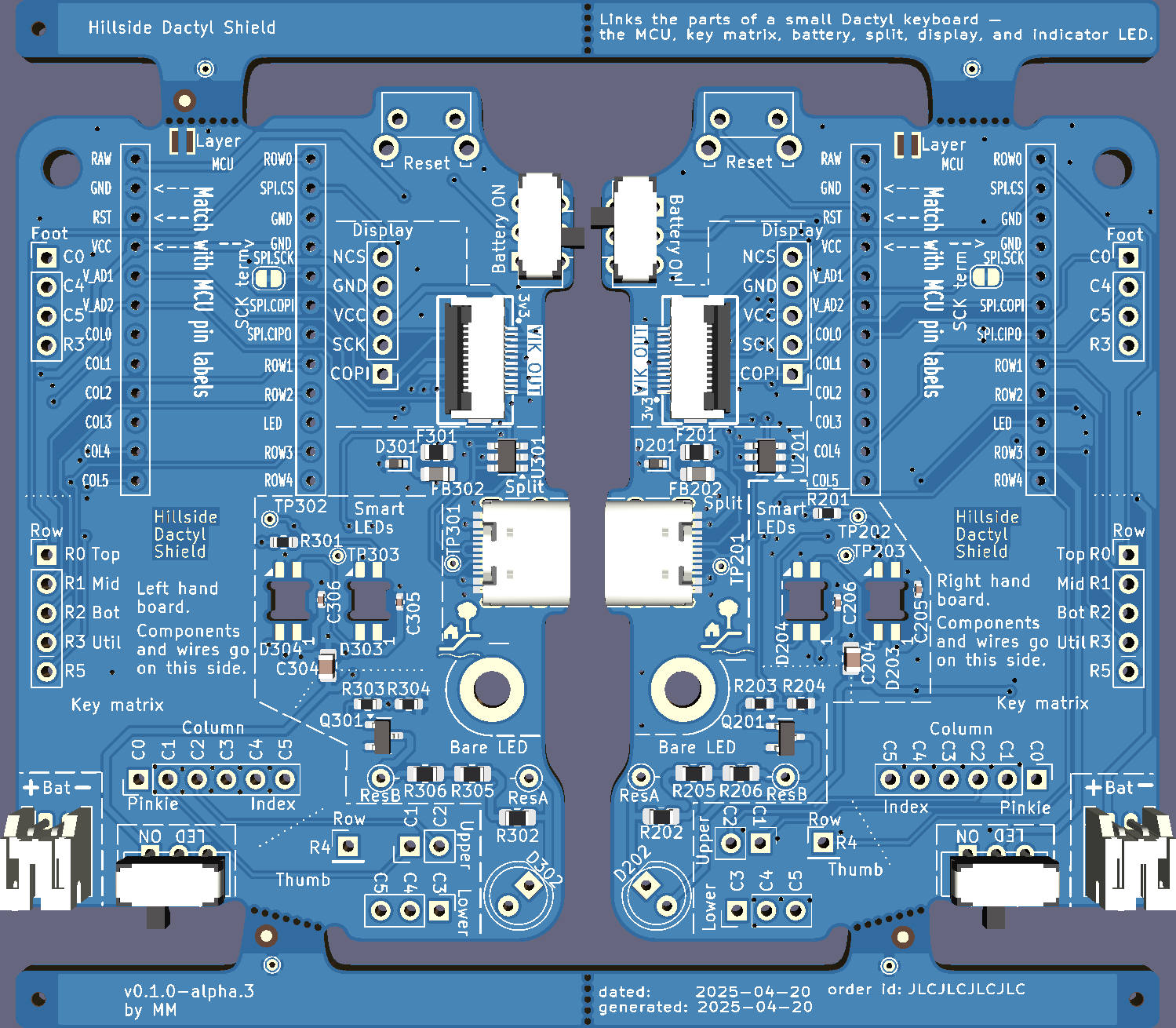 | 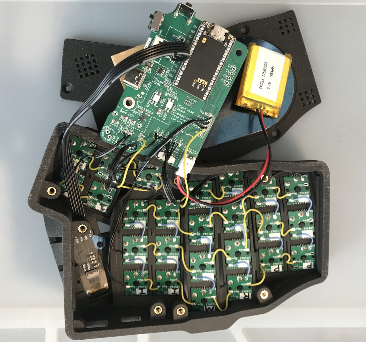 |
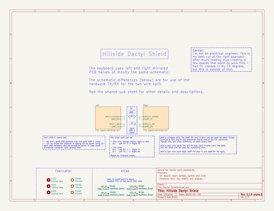
These shields link the parts of a small Dactyl keyboard: the MCU, key matrix, battery, USB-C split, display, and underglow. The shield fits below the index columns and display area of a choc Dactyl keyboard. They should be useful for creating any modest sized Dactyl, but were designed for the Hillside Dactyl 50.
There are three main choice points in a shield cost vs features trade off. See the wiki ordering page for costs.
Our highest priority was a cleanly working key matrix, followed by an informational display or LED. Both with clean signal integrity and a properly low spurious emissions profile. So the key matrix routing came first, followed by SPI routing for the display and LEDs. Best practice for SPI seemed to be a four layer board, as SPI has fast edge transitions on typical keyboard processors. Best practice is also to route high speed signals like SPI first, but I care more about the key matrix, and it seems to have high speed signal edge transitions as well. So our layout is based on four layers with the inner layers as ground. That gives the best signal integrity and hopefully a properly low emissions profile. (The signal integrity in the wires flapping around inside the case is a different question.)
But four layer boards are more expensive in the small batches common with hobbyists. So a two layer fabrication is also possible, as the MCU has direct outer layer ground traces to all ground pin uses. But with two layers, the signal integrity for the matrix, LED, and display is unknown and an improper spurious emissions profile seems likely.
Releases has the files for fabrication.
The wiki has information on parts and ordering. An example of its use in a keyboard can be found in the Hillside Dactyl 50.
The Hillside Dactyl 50, keyboard's ZMK and QMK firmware should be good starting points for creating similar Dactyls.
Some other shields provide related abilities, including:
There is also a STEP file in the GitHub action result files.
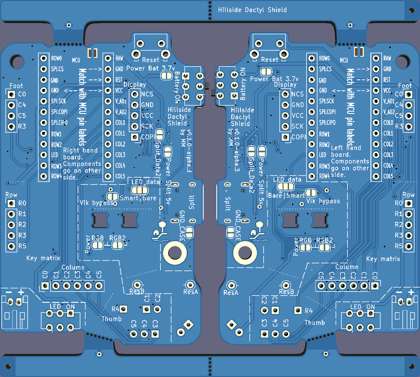
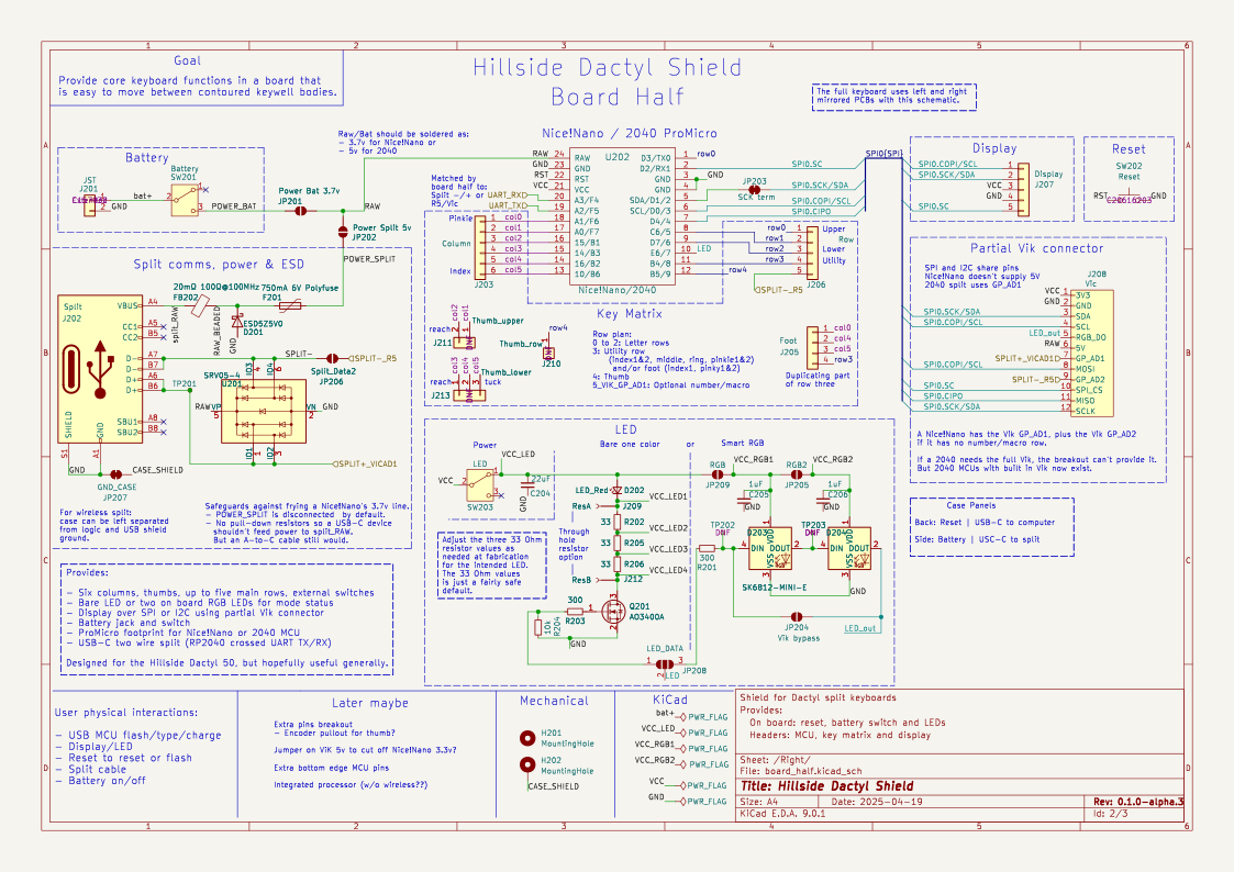
| Qty | Value | Footprint | References |
|---|---|---|---|
| 10 | TestPoint_Small | TestPoint:TestPoint_THTPad_D1.0mm_Drill0.5mm | TP101, TP102, TP103, TP104, TP201, TP202, TP203, TP301, TP302, TP303 |
| 6 | 33 | Resistor_SMD:R_0805_2012Metric_Pad1.20x1.40mm_HandSolder | R202, R205, R206, R302, R305, R306 |
| 4 | 1uF | Capacitor_SMD:C_0402_1005Metric | C205, C206, C305, C306 |
| 4 | 300 | Resistor_SMD:R_0603_1608Metric | R201, R203, R301, R303 |
| 4 | SK6812-MINI-E | Dactyl:SK6812-MINI-E-Dog2_1S | D203, D204, D303, D304 |
| 3 | Fiducial | Dactyl_basics:Fiducial_1mm_Mask2mm | FID101, FID102, FID103 |
| 3 | Tooling Hole | Dactyl_basics:ToolingHole_1.152mm | H101, H102, H103 |
| 2 | 10k | Resistor_SMD:R_0603_1608Metric | R204, R304 |
| 2 | 20mΩ 100Ω@100MHz | Inductor_SMD:L_0805_2012Metric | FB202, FB302 |
| 2 | 22uF | Capacitor_SMD:C_0805_2012Metric | C204, C304 |
| 2 | 750mA 6V Polyfuse | Fuse:Fuse_0805_2012Metric | F201, F301 |
| 2 | AO3400A | Dactyl_basics:SOT-23 | Q201, Q301 |
| 2 | Battery | Dactyl:SW_SPDT_Battery | SW201, SW301 |
| 2 | Column | Dactyl:PinHeader_Columns | J203, J303 |
| 2 | Display | Dactyl:PinHeader_Display | J207, J307 |
| 2 | ESD5Z5V0 | Diode_SMD:D_SOD-523 | D201, D301 |
| 2 | Foot | Dactyl:PinHeader_External | J205, J305 |
| 2 | GND_CASE | Dactyl_basics:SolderJumper-2_P1.3mm_Bridged_RoundedPad1.0x1.5mm | JP207, JP307 |
| 2 | JST | Dactyl:JST_PH_S2B-PH-K_1x02_P2.00mm_Horizontal | J201, J301 |
| 2 | LED | Dactyl:SW_SPDT_JS202011AQN_wider | SW203, SW303 |
| 2 | LED_DATA | Jumper:SolderJumper-3_P1.3mm_Open_RoundedPad1.0x1.5mm | JP208, JP310 |
| 2 | LED_Red | LED_THT:LED_D5.0mm | D202, D302 |
| 2 | MountingHole | MountingHole:MountingHole_3.2mm_M3_DIN965_Pad | H202, H302 |
| 2 | MountingHole | Dactyl_basics:MountingHole_3.2mm_M3_DIN965 | H201, H301 |
| 2 | Nice!Nano/2040 | Dactyl:ProMicro_v2_1S | U202, U302 |
| 2 | Power Bat 3.7v | Dactyl_basics:SolderJumper-2_P1.3mm_Open_RoundedPad1.0x1.5mm | JP201, JP301 |
| 2 | Power Split 5v | Dactyl_basics:SolderJumper-2_P1.3mm_Open_RoundedPad1.0x1.5mm | JP202, JP302 |
| 2 | RGB | Dactyl_basics:SolderJumper-2_P1.3mm_Open_RoundedPad1.0x1.5mm | JP209, JP309 |
| 2 | RGB2 | Dactyl_basics:SolderJumper-2_P1.3mm_Open_RoundedPad1.0x1.5mm | JP205, JP305 |
| 2 | ResA | Dactyl_basics:Conn_Pin_D0.8mm | J209, J309 |
| 2 | ResB | Dactyl_basics:Conn_Pin_D0.8mm | J212, J312 |
| 2 | Reset | Dactyl_basics:SW_Tactile_SKHL_Angled | SW202, SW302 |
| 2 | Row | Dactyl:PinHeader_Rows | J206, J306 |
| 2 | SCK term | Dactyl_basics:SolderJumper-2_P1.3mm_Bridged_RoundedPad1.0x1.5mm | JP203, JP303 |
| 2 | SRV05-4 | Package_TO_SOT_SMD:SOT-23-6 | U201, U301 |
| 2 | Split | Dactyl_basics:USB_C_Receptacle_HRO_TYPE-C-31-M-12 | J202, J302 |
| 2 | Split_Data2 | Dactyl_basics:SolderJumper-2_P1.3mm_Open_RoundedPad1.0x1.5mm | JP206, JP306 |
| 2 | Thumb_lower | Dactyl:PinHeader_Thumb_lower | J213, J313 |
| 2 | Thumb_row | Dactyl:PinHeader_Thumb_row | J210, J310 |
| 2 | Thumb_upper | Dactyl:PinHeader_Thumb_upper | J211, J311 |
| 2 | Vic | Dactyl:vik-keyboard-connector-horizontal | J208, J308 |
| 2 | Vik bypass | Dactyl_basics:SolderJumper-2_P1.3mm_Open_RoundedPad1.0x1.5mm | JP204, JP304 |
The 104 most common of 130 parts.

mmccoyd/hillside
Family of split ergonomic keyboards with three rows of six or five keys and a generous thumb arc

lime7git/rc-piper-transmitter
Radio transmitter for controling RC plane and other devices


Unified-Daughterboard/UDB-S
Narrow variant unified daughterboards for custom keyboard designers and users


jridgewell/HE75
A standard 60% keyboard featuring 75 hall effect keys in an ortholinear layout
It measures 99.4 × 89.3 mm and has 4 copper layers, 1.6 mm thick.
130 parts, built around the SRV05-4, SK6812MINI-EA, AO3400A and ESD5Z5V0. The full list of its parts is on this page, with links to each part's symbol and footprint where PCBKit's library has them.
From the mmccoyd/hillside_dactyl_shield repository on GitHub, at the commit this page was made from: the board is kicad/Dactyl Shield/Dactyl Shield.kicad_pcb and its schematic kicad/Dactyl Shield/Dactyl Shield.kicad_sch. PCBKit opens the board in the browser, with nothing to install.
Its repository publishes it under the CERN-OHL-W-2.0 licence: you may reuse it on that licence's terms (keep the author's notice, and for a copyleft licence share your changes alike).