4 layers160 × 100.1 mm
PMT counter 4 layers
mmazzanti/PMT-counter
A PCB board for counting pulses up to 1.5GHz from a PMT (or similar)
126 parts3GPL-3.0

 mmazzanti/PicoDDS3
A raspberry pico PCB for the AD9854 Analog Devices DDS
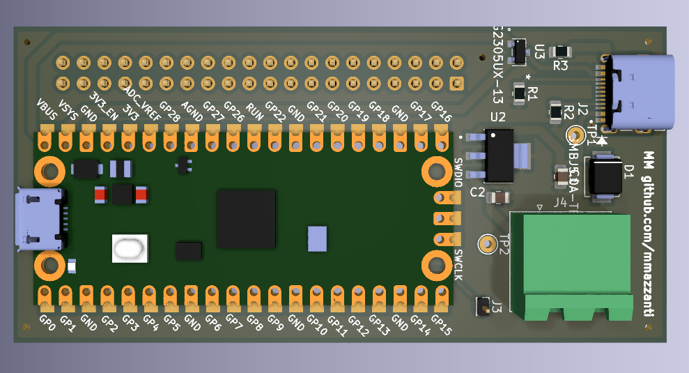
Pi pico AD9854 adapter is an open-source printed circuit board by mmazzanti, from the mmazzanti/PicoDDS repository on GitHub, published under the GPL-3.0 licence. It is a 2-layer board of 38.7 × 80 mm with 15 parts on 74 nets, routed with 156 tracks and 21 vias.
It is built around the DMG2305UX-13, SMBJ5.0A-TR and TYPE-C-31-M-12. Its parts include 4 connectors, 3 resistors, 3 ICs, 2 capacitors and 1 diode. It belongs with the interfaces and adapters boards and the RP2040 boards of this library.


A Raspberry Pico PCB board that can interface with the AD9854 (and similar others) DDS chips or evaluation boards through parallel port.
This new version addresses one of the problems in the previous board (see release 0.9), the limit on the LDO current. The new version includes a LT1086 3.3V capable of up to 1.5A. This LDO version however is slightly obsolete, I would suggest to move to a LT1963A for future. At the moment I'm very satisfied with the version 0.9 and even if the LDO is at its limits and getting quite hot the board performs well since production (~ 4 months ago) in our lab.

This project was inspired by the necessity of having a simple python/serial interface to easily control older DDS evaluation boards (e.g. the Eval-AD9854 here described).
The Eval-AD9854 is an "old" evaluation board for the AD9854 Analog Devices DDS IC. The board permits programming of the AD9854 through a serial or parallel interface.
While the AD9854 is still alive and in production at the time of writing, the word "old" refers to the serial port interface used in the Eval-AD9854 boards.
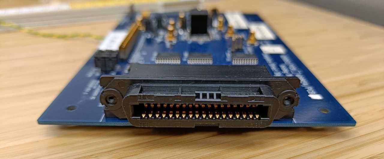
Even though the provided software is not compatible with current Microsoft windows version the hardest part of programming the evaluation board comes from finding a parallel printer cable, perhaps from some electronics "museum".
If you are wondering what the parallel printer port on the Eval-AD9854 looks like, here it is:
Lukily this is not the only interface for programming the evaluation board. A 40 pins IDE port is also available on the board:
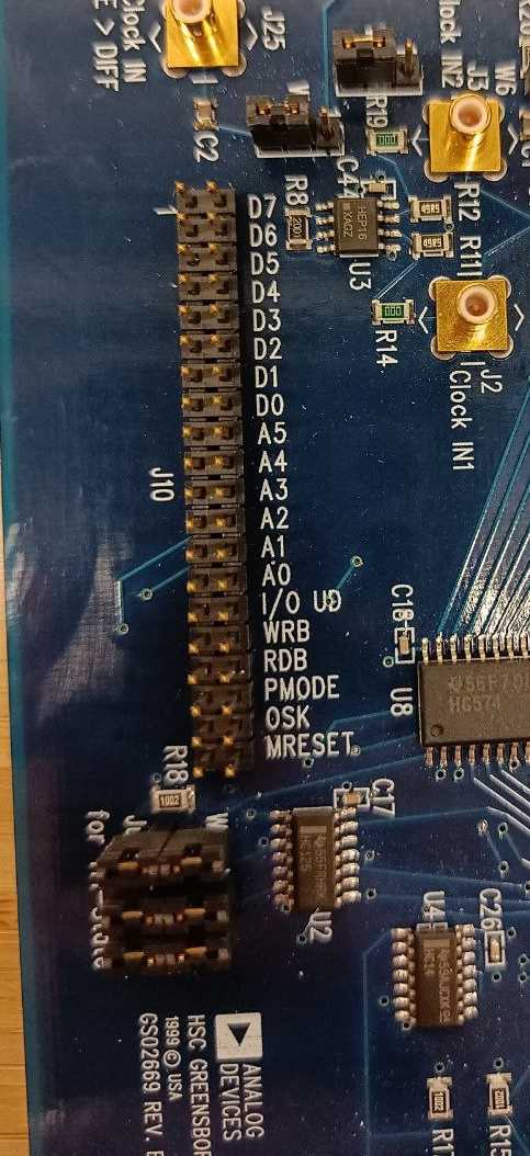
This looks like a perfect match for any Raspberry Pi board! A custom cable from a Raspberry Pi 3/4 to the Eval-9854 board could be made (as I did for the first prototyping), but this will require a cable per each DDS and a lot of soldering. A better idea would be to design a PCB board that interfaces a Raspberry Pi with the DDS evaluation board.
Sure, any microcontroller capable of handling 21 digital pins can do the job. I decided on a Raspberry Pico just because of its price tag and small form factor.
The evaluation board needs a 3.3V power source to operate. This can also be provided by the same Raspberry. BEWARE The Eval-9854 can request up to 1A of current at 3.3V, not all Raspberry pi boards can source that amount of power. When not using the sinc filtering function of the DDS the power consumption goes reduces to ~750mA, when prototyping I used a Raspberry pi 400 and it handled the power hungry DDS quite decently. I would however suggest to power this board externally. The PCB board in this repository takes care also of that. I added a 1A LDO with a screw terminal where one can connect power cables to the Eval-9854; not very elegant, I know,but practical.
Once you are in possession of a PicoDDS board you will have to load on the Raspberry Pico the python source file that you find in the /src folder. The programming of the Pico happens through its micro USB connection. The USB connection on the board is only for powering the Pico and the Eval-9854; it cannot be used to transfer data to the board!!
First load a UF2 micropython image on your board (guide here) then load the /src/main.py script on your board. You can do that using Thonny, VS code or whatever IDE is now in vogue.
The AD9854 permits various modes of operation:
More precise description can be found on the AD9854 datasheet.
My tipycal day usage of the AD9854 is to drive some AOM in our laboratory (check out here why we want to do that).
An AOM (Acousto Optic Modulator) is nothing more than a cyrstal vibrating at a certain frequency capable of steering a laser beam and adding-subtracting its resonating frequency to the diffracting beam (read more here ).
The typical resonating frequencies of AOM are between 70-300MHz although the coverage of this bandwith is mostly wavelength dependent.
In my case I needed a signal at 150MHz and I appeared to have found some Eval-AD9854 boards in some "storage" around (what a lucky find :blush: )
One of the parameters hard coded in the main.py file is the clocking speed. The AD9854 can be clocked at 300MHz max. It has an internal PLL clock multiplier in case only slower clocks are available. The board I've been using so far has a 60MHz oscillator on it, however for more phase-dependent applications I plan to use a 10MHz clock reference from an atomic clock in future. The maximum clock multiplier is 20 that would mean that using directly a 10MHz clock and a x20 multiplier will push my clocking speed to 200MHz. In this case one can use a second DDS to generate a higher frequency clock or a second PLL clock multiplier.
Set the following variables depending on your clocking speed :
Various functions are available from the source script. These don't cover all the capabilities of the AD9854 but only what I need in the lab. More functions might be added in the future if I need them. Feel free to fork this repository if you want to add more!
After connecting to the Pico the following functions are available from the serial terminal.
Then no problem, the board just simplifies the connection. If you don't want to order a board or just test if the DDS works for you or any other reasons you can just connect 20 of the 40 pins connection to your Raspberry Pico (or 3/4) and start using generating RF frequencies immediately!
BEWARE : powering the DDS is now up to you. Find a 3.3V 1A power source (better if 1.5A).
Connect the Pico and the Eval-9854 as following:
Or replace the Pins number in the python source file. A Raspberry pico can be connected using dupont wires as following :
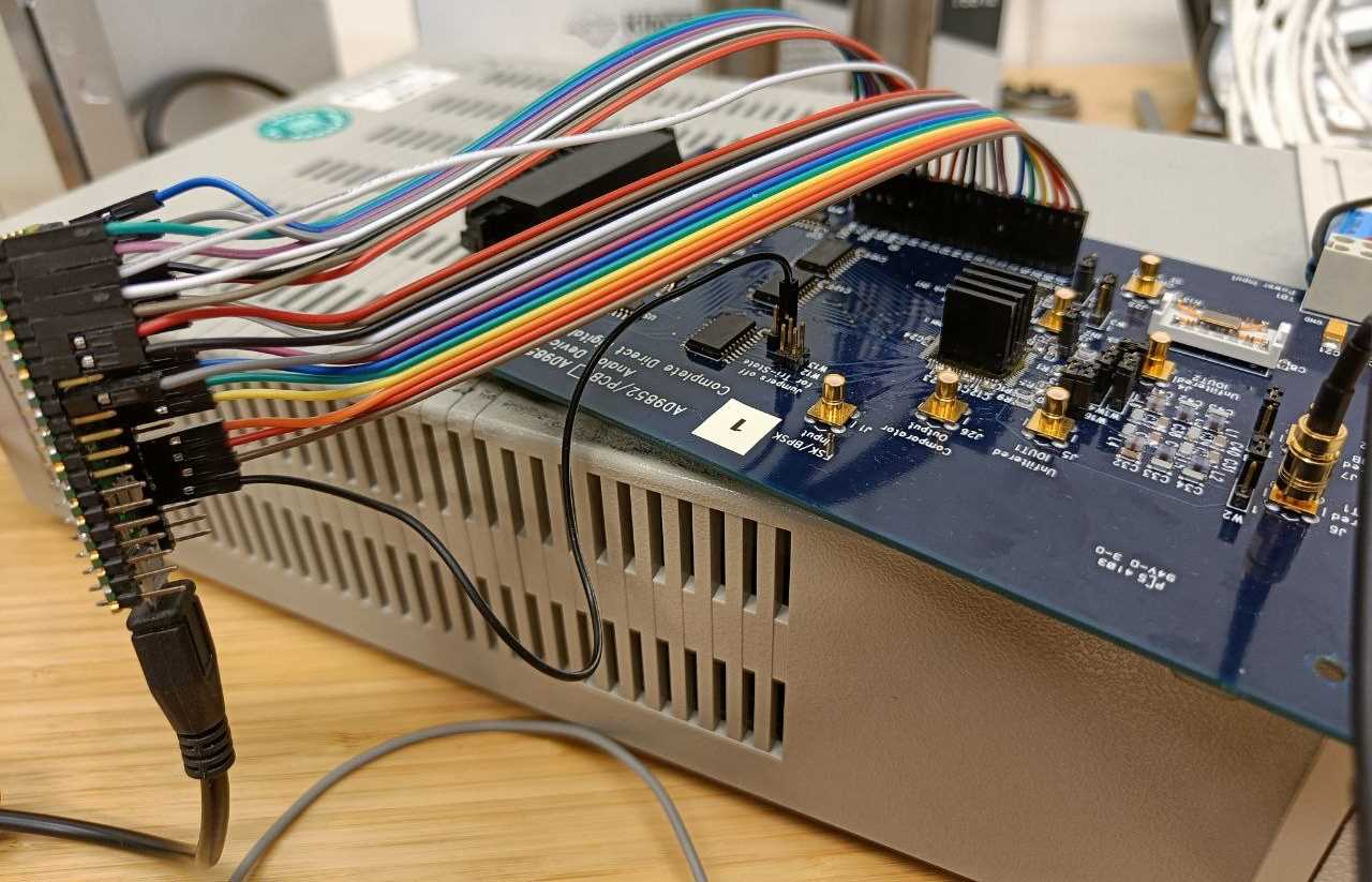
Notice the black wire going on the pin W9, this is used for the FSK bit.
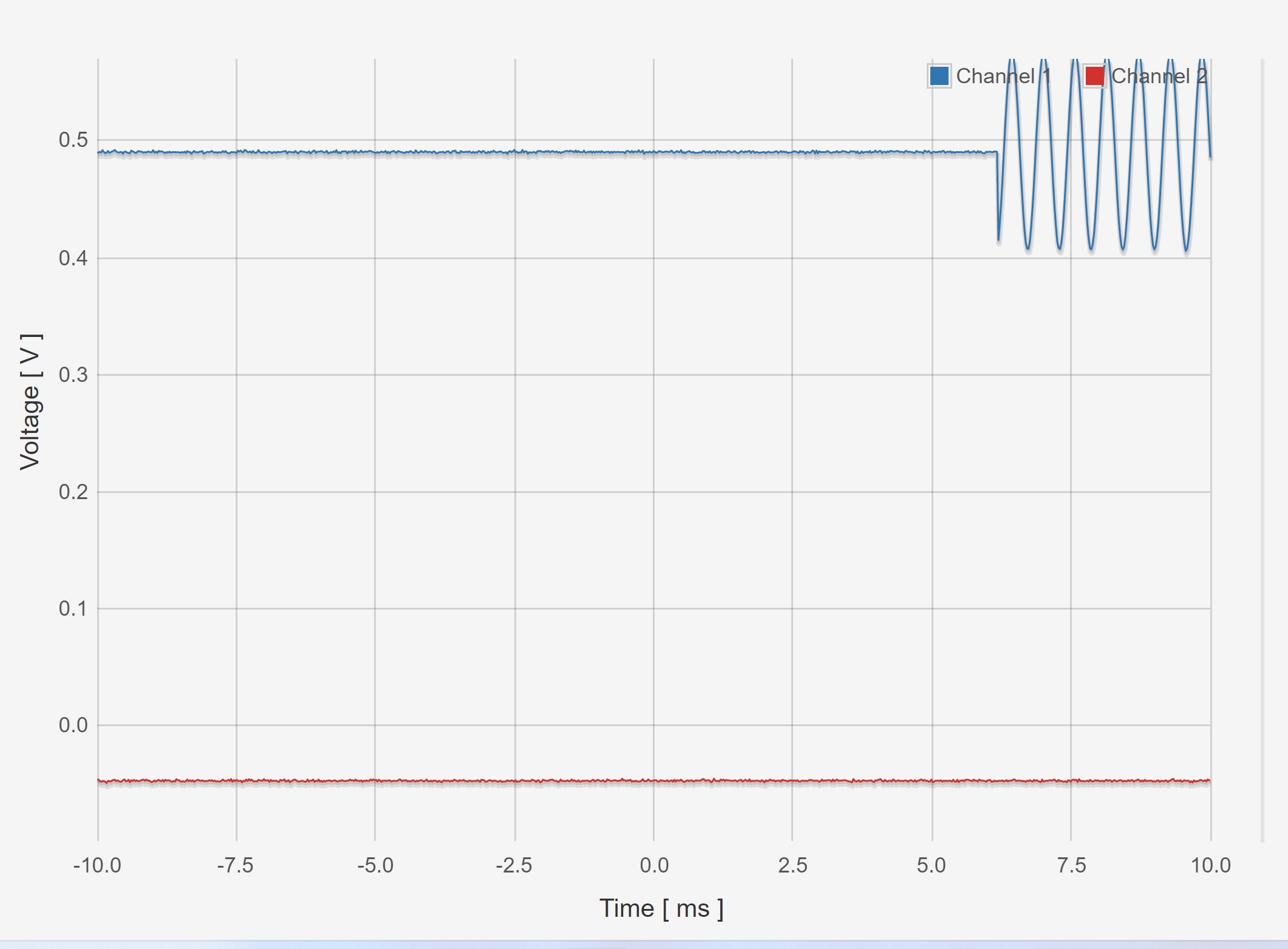
Time required to switch off -> on the RF signal.
It takes ~6ms from the moment one calls the on(freq,ampl) (T=0 in the picture) to the moment when the AD9854 gives an output.
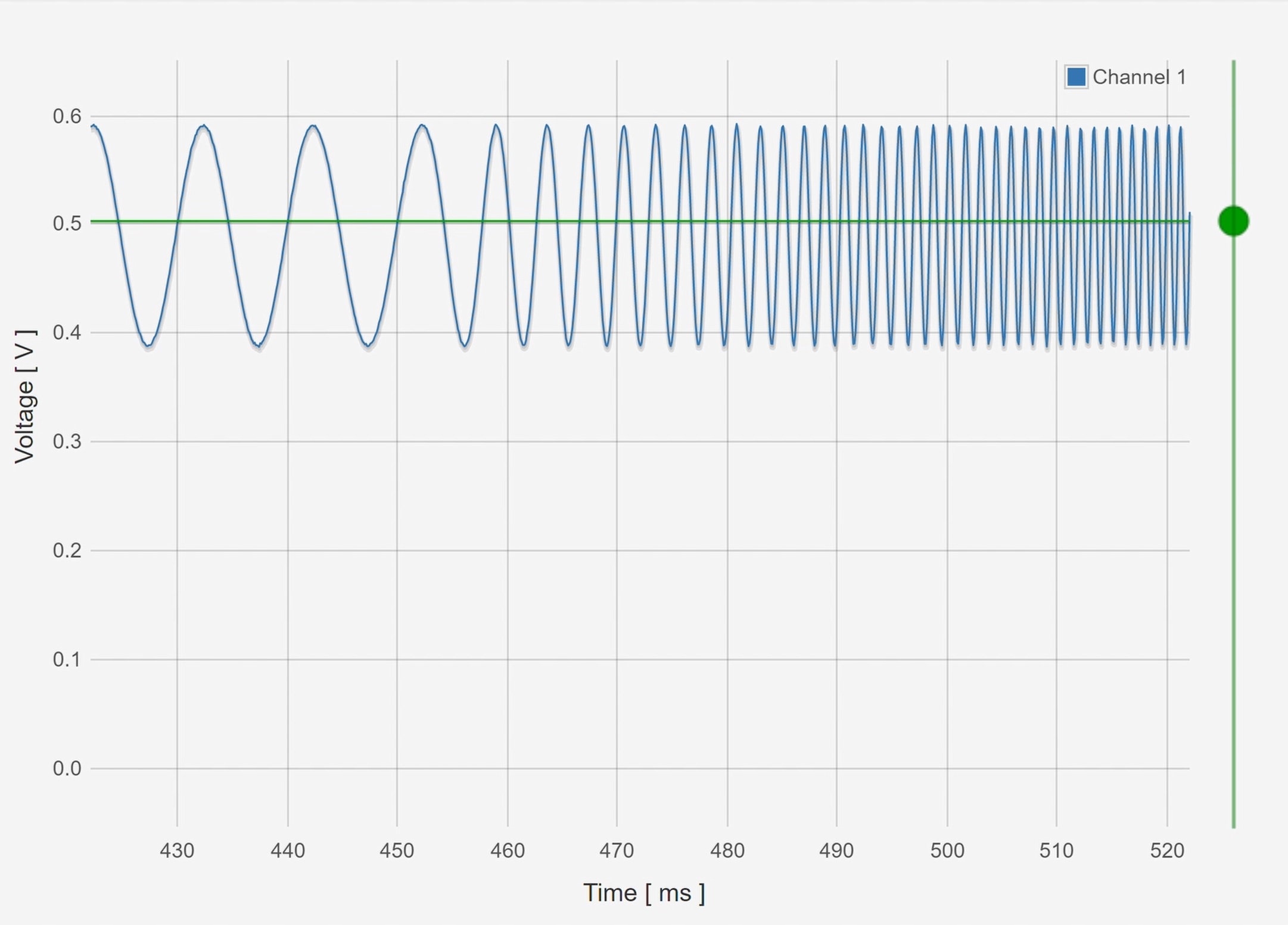
This is an example of a frequency sweep :
| Qty | Value | Footprint | References |
|---|---|---|---|
| 2 | 10uF | Capacitor_Tantalum_SMD:CP_EIA-2012-12_Kemet-R | C1, C2 |
| 2 | 5.1k | Resistor_SMD:R_0805_2012Metric | R1, R2 |
| 2 | TestPoint | TestPoint:TestPoint_THTPad_D2.0mm_Drill1.0mm | TP1, TP2 |
| 1 | 0 | Resistor_SMD:R_0805_2012Metric | R3 |
| 1 | Conn_01x01_Male | Connector_Pin:Pin_D1.0mm_L10.0mm | J3 |
| 1 | Conn_02x20_Odd_Even | Connector_IDC:IDC-Header_2x20_P2.54mm_Vertical | J1 |
| 1 | DMG2305UX-13 | footprints:DMG2305UX-13 | U3 |
| 1 | LT1086-3.3 | LT1086:LT1086 | U2 |
| 1 | Pico | MCU_RaspberryPi_and_Boards:RPi_Pico_SMD_TH | U1 |
| 1 | SMBJ5.0A-TR | SMBJ5-0A-TR:SMBJ5.0A-TR | D1 |
| 1 | Screw_Terminal_01x02 | Connector_Phoenix_MSTB:PhoenixContact_MSTBA_2,5_2-G-5,08_1x02_P5.08mm_Horizontal | J4 |
| 1 | TYPE-C-31-M-12 | TYPE-C-31-M-12:HRO_TYPE-C-31-M-12 | J2 |
mmazzanti/PMT-counter
A PCB board for counting pulses up to 1.5GHz from a PMT (or similar)

ehasunchy/kicad-pcb-projects
KiCad PCB design portfolio featuring ESP32 IoT hardware, power regulation, USB interfaces, schematics, PCB layouts, and manufacturing files.

soldernerd/InclinationMeter
A battery-powered, Bluetooth-enabled precision electronic level instrument for machine tool geometry inspection and granite surface plate qualification.

sequoia-hope/rpi-cm4-switch-board
A Raspberry Pi (RPi) Compute Module 4 (CM4) Carrier Board with integrated gigabit switch

hemna/cm4-digipi-carrier
Raspberry Pi CM4 Carrier board for Ham radio PTT Control


CV19CO/open_controller_for_ventilator
Open source controller for ventilators
It measures 38.7 × 80 mm and has 2 copper layers, 1.6 mm thick.
15 parts, built around the DMG2305UX-13, SMBJ5.0A-TR and TYPE-C-31-M-12. The full list of its parts is on this page, with links to each part's symbol and footprint where PCBKit's library has them.
From the mmazzanti/PicoDDS repository on GitHub, at the commit this page was made from: the board is PCB/Pi-pico-AD9854_adapter.kicad_pcb and its schematic PCB/Pi-pico-AD9854_adapter.kicad_sch. PCBKit opens the board in the browser, with nothing to install.
Its repository publishes it under the GPL-3.0 licence: you may reuse it on that licence's terms (keep the author's notice, and for a copyleft licence share your changes alike).