
4 layers299 × 127 mm

 mlyle/armtrainer24
ARM "Microprocessor Trainer" code base
MicroTrainer is an open-source printed circuit board by mlyle, from the mlyle/armtrainer repository on GitHub, published under the BSD-2-Clause licence. It is a 4-layer board of 135 × 118 mm with 68 parts on 65 nets, routed with 437 tracks and 89 vias.
It is built around the LP5907MFX-3.3. Its parts include 23 switches, 12 capacitors, 12 resistors, 4 connectors and 2 ICs. It belongs with the STM32 boards of this library.
This is a minimal monitor and and hardware stack for a small microcontroller trainer board, that was used to teach a Computer Organization class to students from ages 11-14.
Microprocessor trainers were a commonplace tool used to learn computing in the 1970s and early 1980s. They replicated the console found on minicomputers, and allowed engineers to gain experience writing programs in machine code.
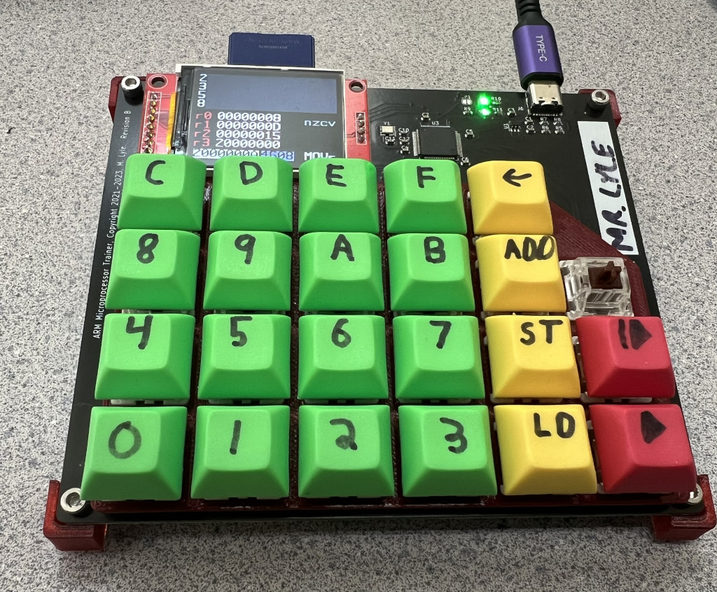
The Computer Organization class that I taught was a "how computers work" class with minimal use of conventional computers in the classroom. We focused initially on gates, building from there to understand simple combinatorial and sequential circuits, and eventually ALUs, register files, and microprocessor subsystems. This culminated in a study of ARM-Thumb machine code.
ARM-Thumb machine code was a fairly ideal architecture for students to learn, because:
src/ and inc/ contain the trainer firmware.hw/ contains the KiCad hardware designs and manufacturing outputs.arm-manual/ contains the student manual sources.examples/ contains programs captured from trainers during class.tools/ contains host-side conversion, disassembly, capture, and printing tools.Run make tools to build the host-side utilities in build/tools/. The classroom
scripts should be run from any directory; they locate the repository and examples
automatically.
By a student, Robin K:
20000000	DF20		(clear screen)
20000002	2001		(mov r0, #1)
20000004	2102		(mov r1, #1)
20000006	180A		(add r2, r0, r1)
20000008	DF21		(print contents of register 0)
2000000A	4608		(mov r0, r1)
2000000C	4611		(mov r1, r2)
2000000E E7FA (b 20000006)| Qty | Value | Footprint | References |
|---|---|---|---|
| 8 | 5.1k | Resistor_SMD:R_0603_1608Metric | R1, R2, R3, R4, R5, R6, R9, R12 |
| 8 | MountingHole | MountingHole:MountingHole_3.2mm_M3 | H1, H2, H3, H4, H5, H6, H7, H8 |
| 6 | 0.1uF | Capacitor_SMD:C_0603_1608Metric | C2, C4, C5, C6, C7, C12 |
| 4 | 2.2uF | Capacitor_SMD:C_0603_1608Metric | C1, C3, C8, C9 |
| 3 | Fiducial | Fiducial:Fiducial_1mm_Mask2mm | FID1, FID2, FID3 |
| 2 | 10 | Resistor_SMD:R_0603_1608Metric | R7, R8 |
| 2 | 12pF | Capacitor_SMD:C_0603_1608Metric | C10, C11 |
| 2 | 330 | Resistor_SMD:R_0603_1608Metric | R10, R11 |
| 2 | LED | LED_SMD:LED_0805_2012Metric | D1, D2 |
| 1 | 25MHz | Crystal:Crystal_SMD_3225-4Pin_3.2x2.5mm | Y1 |
| 1 | BootJumper | Jumper:SolderJumper-2_P1.3mm_Open_RoundedPad1.0x1.5mm | JP1 |
| 1 | Conn_01x04 | Connector_PinSocket_2.54mm:PinSocket_1x04_P2.54mm_Vertical | J4 |
| 1 | Conn_01x08 | Connector_PinSocket_2.54mm:PinSocket_1x08_P2.54mm_Vertical | J5 |
| 1 | Conn_ARM_SWD_TagConnect_TC2030 | Connector:Tag-Connect_TC2030-IDC-FP_2x03_P1.27mm_Vertical | J1 |
| 1 | KEY_0 | Button_Switch_Keyboard:SW_Cherry_MX_1.00u_PCB | SW19 |
| 1 | KEY_1 | Button_Switch_Keyboard:SW_Cherry_MX_1.00u_PCB | SW20 |
| 1 | KEY_2 | Button_Switch_Keyboard:SW_Cherry_MX_1.00u_PCB | SW21 |
| 1 | KEY_3 | Button_Switch_Keyboard:SW_Cherry_MX_1.00u_PCB | SW22 |
| 1 | KEY_4 | Button_Switch_Keyboard:SW_Cherry_MX_1.00u_PCB | SW13 |
| 1 | KEY_5 | Button_Switch_Keyboard:SW_Cherry_MX_1.00u_PCB | SW14 |
| 1 | KEY_6 | Button_Switch_Keyboard:SW_Cherry_MX_1.00u_PCB | SW15 |
| 1 | KEY_7 | Button_Switch_Keyboard:SW_Cherry_MX_1.00u_PCB | SW16 |
| 1 | KEY_8 | Button_Switch_Keyboard:SW_Cherry_MX_1.00u_PCB | SW7 |
| 1 | KEY_9 | Button_Switch_Keyboard:SW_Cherry_MX_1.00u_PCB | SW8 |
| 1 | KEY_A | Button_Switch_Keyboard:SW_Cherry_MX_1.00u_PCB | SW9 |
| 1 | KEY_ADDR | Button_Switch_Keyboard:SW_Cherry_MX_1.00u_PCB | SW11 |
| 1 | KEY_B | Button_Switch_Keyboard:SW_Cherry_MX_1.00u_PCB | SW10 |
| 1 | KEY_C | Button_Switch_Keyboard:SW_Cherry_MX_1.00u_PCB | SW1 |
| 1 | KEY_CLR | Button_Switch_Keyboard:SW_Cherry_MX_1.00u_PCB | SW5 |
| 1 | KEY_D | Button_Switch_Keyboard:SW_Cherry_MX_1.00u_PCB | SW2 |
| 1 | KEY_E | Button_Switch_Keyboard:SW_Cherry_MX_1.00u_PCB | SW3 |
| 1 | KEY_F | Button_Switch_Keyboard:SW_Cherry_MX_1.00u_PCB | SW4 |
| 1 | KEY_LOAD | Button_Switch_Keyboard:SW_Cherry_MX_1.00u_PCB | SW23 |
| 1 | KEY_RST | Button_Switch_Keyboard:SW_Cherry_MX_1.00u_PCB | SW25 |
| 1 | KEY_RUN | Button_Switch_Keyboard:SW_Cherry_MX_1.00u_PCB | SW24 |
| 1 | KEY_STEP | Button_Switch_Keyboard:SW_Cherry_MX_1.00u_PCB | SW18 |
| 1 | KEY_STOR | Button_Switch_Keyboard:SW_Cherry_MX_1.00u_PCB | SW17 |
| 1 | LP5907MFX-3.3 | Package_TO_SOT_SMD:SOT-23-5 | U1 |
| 1 | STM32F411R_C-E_Tx | Package_QFP:LQFP-64_10x10mm_P0.5mm | U3 |
| 1 | USB_C_Receptacle_USB2.0 | Connector_USB:USB_C_Receptacle_G-Switch_GT-USB-7010ASV | J6 |
It measures 135 × 118 mm and has 4 copper layers, 1.6 mm thick.
68 parts, built around the LP5907MFX-3.3. The full list of its parts is on this page, with links to each part's symbol and footprint where PCBKit's library has them.
From the mlyle/armtrainer repository on GitHub, at the commit this page was made from: the board is hw/MicroTrainer.kicad_pcb and its schematic hw/MicroTrainer.kicad_sch. PCBKit opens the board in the browser, with nothing to install.
Its repository publishes it under the BSD-2-Clause licence: you may reuse it on that licence's terms (keep the author's notice, and for a copyleft licence share your changes alike).

jerry20091103/Teensy_Grovebox
A portable synth and music multi-tool made with Teensy 4.1


Mew463/esp32-caliper
It features a built in 150mAh battery and a USB C interface for charging/uploading code.


will127534/RPI5-SDexpress-Hat
ctrl-c "RPI5-CFE-Hat" ctrl-v "RPI5-SDexpress-Hat"


ATmega8/kiterf
Release KiteRF is a SDR system with K210 & FPGA & ESP32 as its core controller, which make SDR more intelligent, portable and cheap.