
2 layers52.2 × 52.2 mm
Base promicro
google/mozc-devices
Circuit diagrams and firmware source code for Gboard DIY keyboards
30 parts3kApache-2.0
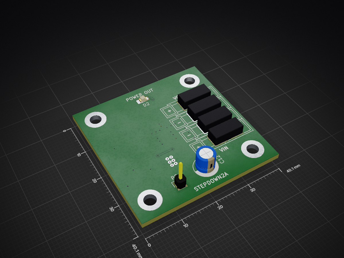
 mlab-modules/STEPDOWN02
28V input 1 MHz switching step-down converter
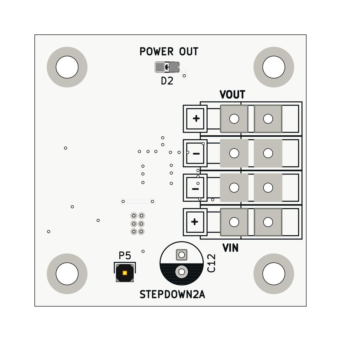
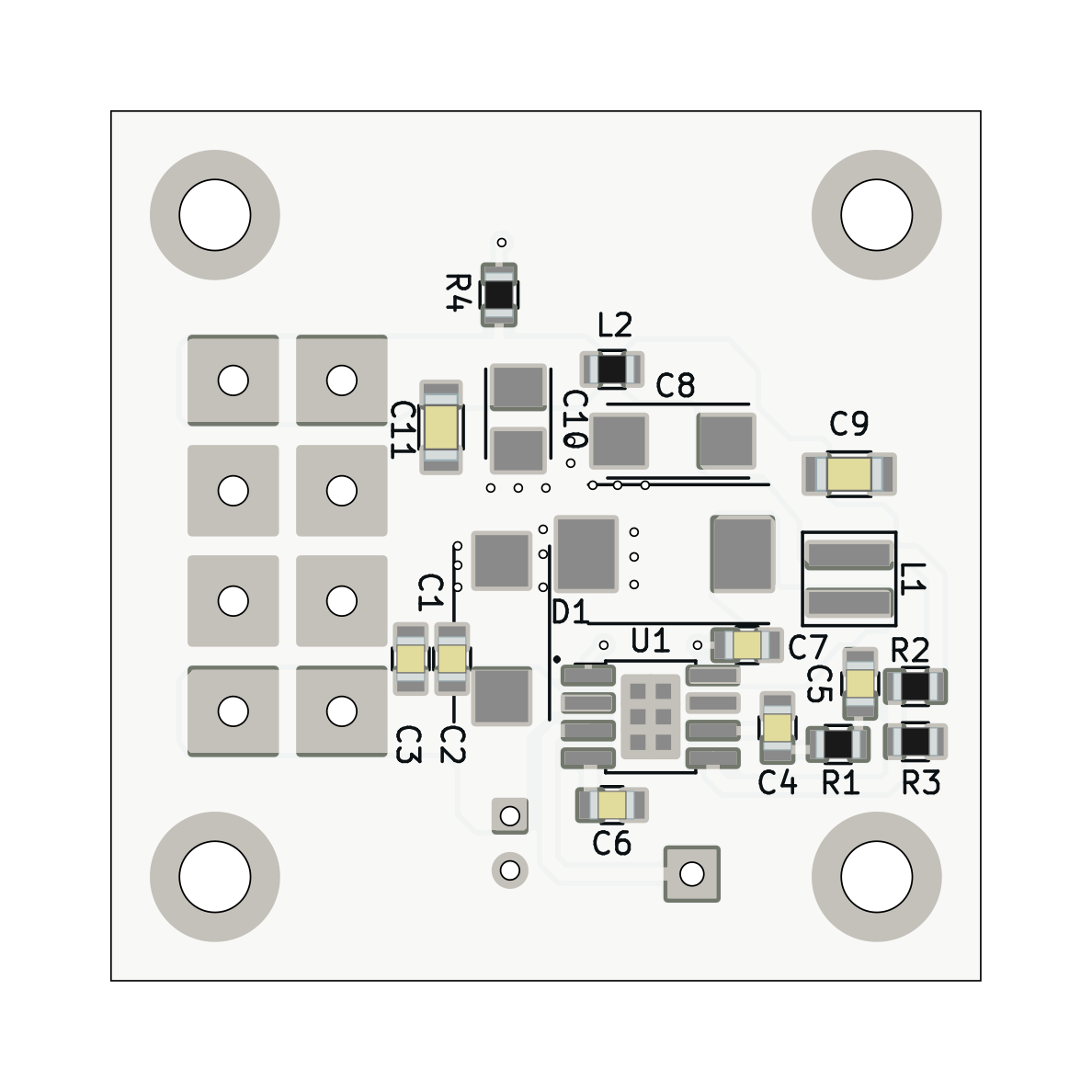
STEPDOWN02 is an open-source printed circuit board by mlab-modules, from the mlab-modules/STEPDOWN02 repository on GitHub, published under the GPL-3.0 licence. It is a 2-layer board of 40.1 × 40.1 mm with 30 parts on 12 nets, routed with 103 tracks and 28 vias.
It is built around the TPS54332DDA. Its parts include 12 capacitors, 9 connectors, 4 resistors, 2 diodes and 2 inductors. It belongs with the power boards of this library.
This repository contains the design files, documentation, and usage instructions for the TPS54332 MLAB module. The TPS54332 is a high-efficiency synchronous buck converter capable of delivering up to 3 A of continuous output current. This development module is designed to integrate the TPS54332 into MLAB projects with ease.
To use this development module, you will need:
| Qty | Value | Footprint | References |
|---|---|---|---|
| 4 | CONN1_1 | Connect:WAGO256 | J1, J2, J3, J4 |
| 4 | _NC | Mounting_Holes:MountingHole_3.2mm_M3_DIN965_Pad | P1, P2, P3, P4 |
| 2 | 1u5 | Capacitors_SMD:C_1206 | C9, C11 |
| 1 | 100n | Capacitors_SMD:C_0805 | C7 |
| 1 | 10k2 | Resistors_SMD:R_0805 | R2 |
| 1 | 18pF | Capacitors_SMD:C_0805 | C4 |
| 1 | 1k2 | Resistors_SMD:R_0805 | R4 |
| 1 | 1k93 | Resistors_SMD:R_0805 | R3 |
| 1 | 1u | Capacitors_SMD:C_0805 | C3 |
| 1 | 22u | Capacitors_Tantalum_SMD:TantalC_SizeB_EIA-3528_Reflow | C10 |
| 1 | 22u | Capacitors_Tantalum_SMD:TantalC_SizeD_EIA-7343_Reflow | C1 |
| 1 | 22u | Capacitors_Tantalum_SMD:TantalC_SizeC_EIA-6032_Reflow | C8 |
| 1 | 240nH | Resistors_SMD:R_0805 | L2 |
| 1 | 35k7 | Resistors_SMD:R_0805 | R1 |
| 1 | 3u3 | Capacitors_SMD:C_0805 | C2 |
| 1 | 4.7uH | Inductors_NEOSID:Inductor_XAL4030-472MEB | L1 |
| 1 | 47u | Capacitors_ThroughHole:C_Radial_D6.3_L11.2_P2.5 | C12 |
| 1 | 680pF | Capacitors_SMD:C_0805 | C5 |
| 1 | 8n2 | Capacitors_SMD:C_0805 | C6 |
| 1 | CONN_01X01 | Pin_Headers:Pin_Header_Straight_1x01 | P5 |
| 1 | D_Schottky | Diodes_SMD:DO-214AB | D1 |
| 1 | POWER OUT | LEDs:LED_0805 | D2 |
| 1 | TPS54332 | Housings_SOIC:8-PowerSOIC_Pitch1.27mm | U1 |
It measures 40.1 × 40.1 mm and has 2 copper layers, 1.6 mm thick.
30 parts, built around the TPS54332DDA. The full list of its parts is on this page, with links to each part's symbol and footprint where PCBKit's library has them.
From the mlab-modules/STEPDOWN02 repository on GitHub, at the commit this page was made from: the board is hw/sch_pcb/STEPDOWN02.kicad_pcb and its schematic hw/sch_pcb/STEPDOWN02.kicad_sch. PCBKit opens the board in the browser, with nothing to install.
Its repository publishes it under the GPL-3.0 licence: you may reuse it on that licence's terms (keep the author's notice, and for a copyleft licence share your changes alike).
google/mozc-devices
Circuit diagrams and firmware source code for Gboard DIY keyboards


VoronDesign/Voron-Hardware
Cool Hardware designed by the Voron Design group

hoglet67/RGBtoHDMI
Bare-metal Raspberry Pi project that provides pixel-perfect sampling of Retro Computer RGB/YUV video and conversion to HDMI

tenderlove/initial-v
It's a BMW shifter converted to a Bluetooth Keyboard that you use with Vim

hackclub/OnBoard
💡 Join 1,000 teenagers and make your first PCB with a $100 grant!

