Skip to the content
PCBKitNew board
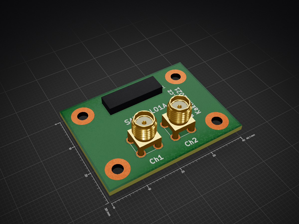
2 layers40.1 × 30 mmSATABAL01, the printed circuit board in 3D

RF balun with unballanced MCX/SMA and balanced SATA connectors

Size
40.1 × 30 mm
Copper layers
2
Thickness
1.6 mm
Parts
9
Nets
9
Pads
33
Tracks, vias
18, 0
Pours
1
Routed
Yes
KiCad
KiCad 9.0 (file 20241229)
Created
28 Apr 2021
Updated
20 Dec 2025

Overview

SATABAL01 is an open-source printed circuit board by mlab-modules, from the mlab-modules/SATABAL01 repository on GitHub, published under the GPL-3.0 licence. It is a 2-layer board of 40.1 × 30 mm with 9 parts on 9 nets, routed with 18 tracks and 0 vias.

It is built around the ETC1-1-13. It belongs with the radio and wireless boards of this library.

Main components

1

README

README.md

SATABAL01 - passive coax to SATA balun module

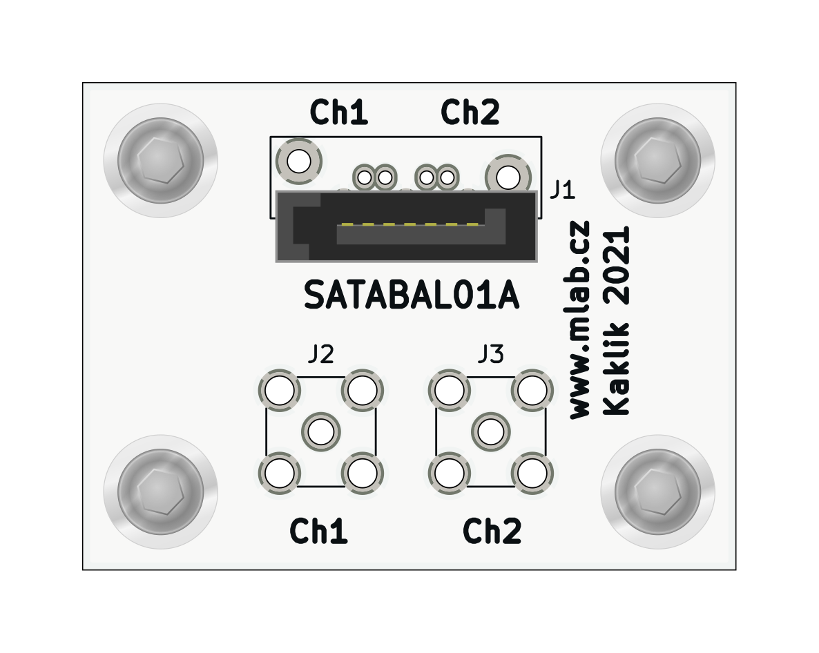
SATABAL01 is a passive RF balun module designed to interface high-speed differential pairs used in SATA data lines with unbalanced coaxial transmission lines. This module is primarily intended for applications requiring measurement, testing, or signal routing of SATA signals over RF-grade coaxial cables.

SATABAL01 Top view

Features

  • Converts differential SATA signals to unbalanced RF signals and vice versa
  • Suitable for signal bandwidths from 4.5 MHz to 3000 MHz
  • Dual-channel design for full SATA differential pair
  • Standard SATA connector (J1)
  • MCX or SMA coaxial connectors (J2, J3)
  • Uses Mini-Circuits TC1-1-13MX+ wideband RF balun transformers
  • Compact design suitable for integration into test setups or embedded systems

Functional Description

The module contains two identical wideband RF balun transformers (Mini-Circuits TC1-1-13MX+), each used to convert one differential signal pair to a single-ended signal. The SATA connector (J1) provides two differential pairs. Each pair is routed through a balun (T1, T2), with the single-ended outputs available at connectors J3 and J2 respectively. These connectors support either MCX or SMA types depending on user preference.

Electrical Specifications (Per Channel)

Based on the TC1-1-13MX+ balun:

  • Impedance Ratio: 1:1
  • Frequency Range: 4.5 MHz to 3000 MHz
  • Insertion Loss:
    • 4.5–1000 MHz: typ. 1.0 dB
    • 1000–2000 MHz: typ. 2.0 dB
    • 2000–3000 MHz: typ. 3.0 dB
  • Amplitude Unbalance: typ. 0.5 dB (up to 2000 MHz)
  • Phase Unbalance: typ. 2–3 degrees (up to 2000 MHz)

Refer to the TC1-1-13MX+ datasheet for detailed transformer characteristics【7†source】.

Schematic Overview

  • J1: SATA 7-pin connector (AMP 67491-1030)
  • T1, T2: Mini-Circuits TC1-1-13MX+ transformers for each differential pair
  • J2, J3: Output via MCX/SMA connectors
  • H1–H4: Mounting pads and ground.

Typical Use Cases

  • Probing SATA lines with RF measurement equipment
  • High-frequency signal transmission over coaxial cable
  • Balancing/unbalancing of high-speed digital signals and clock

Assembly Notes

  • Ensure correct orientation of baluns as per datasheet marking.
  • Match connector types (MCX or SMA) to your coaxial cabling needs.
  • Use controlled impedance traces for differential signal integrity.

Parts

9
QtyValueFootprintReferences
4PadMlab_Mechanical:MountingHole_3mmH1, H2, H3, H4
2Conn_Coaxial SMA or MCXConnector_Coaxial:SMA_Amphenol_901-144_VerticalJ2, J3
2ETC1-1-13Transformer_SMD:Transformer_MACOM_SM-22T1, T2
1SATA7-67491-1030Mlab_CON:SATA-7_THT_VERT_2J1

Questions

How big is the SATABAL01 PCB?

It measures 40.1 × 30 mm and has 2 copper layers, 1.6 mm thick.

What parts does the SATABAL01 use?

9 parts, built around the ETC1-1-13. The full list of its parts is on this page, with links to each part's symbol and footprint where PCBKit's library has them.

Where can I download the SATABAL01 KiCad files?

From the mlab-modules/SATABAL01 repository on GitHub, at the commit this page was made from: the board is hw/sch_pcb/SATABAL01.kicad_pcb and its schematic hw/sch_pcb/SATABAL01.kicad_sch. PCBKit opens the board in the browser, with nothing to install.

Can I use the SATABAL01 design in my own project?

Its repository publishes it under the GPL-3.0 licence: you may reuse it on that licence's terms (keep the author's notice, and for a copyleft licence share your changes alike).

Similar boards

  • 2 layersQFHBAL01, the printed circuit board in 3D

    QFHBAL01

    ODZ-UJF-AV-CR/QFHBAL01

    Balun for QFH antennas. Antenna structure should be 3D printed.

    10 parts6GPL-3.0
  • 4 layers69.6 × 43.5 mmZturn adc, the printed circuit board in 3D

    Zturn adc

    formalism/zturn-adc-fm-rx

    FM radio reciever by custom ADC/FM BPF board and Zturn board.

    109 parts5
  • 4 layers127 × 101.6 mmS Band Transceiver, the printed circuit board in 3D

    S Band Transceiver

    tkeller12/openEPR

    Open-Source EPR Spectrometer

    224 parts1MIT
  • 2 layers66.5 × 77.7 mmPiRadio, the printed circuit board in 3D

    PiRadio

    hanak2/KiCAD_work

    136 parts
  • 4 layers113 × 70.1 mmFull Board, the printed circuit board in 3D

    Full Board

    lballard9/GTRF-PCB

    103 parts
  • 6 layers160 × 100 mmModulator V1p2, the printed circuit board in 3D

    Modulator V1p2

    sOrzada/STASIS_Exposure_Hardware

    This is the repository for the exposition hardware of the STASIS project.

    114 partsCERN-OHL-W-2.0
  • 4 layers66 × 155 mmWK-3, the printed circuit board in 3D

    WK-3

    zOnlyKroks/pcb-consortium

    339 partsCC0-1.0
  • 2 layers103 × 30.5 mmTS Back Endcap, the printed circuit board in 3D

    TS Back Endcap

    EEVengers/ThunderScope

    ThunderScope GitHub Repo

    9 parts1.3kMIT