
4 layers20.3 × 45.5 mm
SX1257-PMOD
xil-se/SX1257-PMOD
This is a PMOD built around the SX1257 transceiver. It uses an I2C-SPI bridge (SC18IS602B) since only 8 io pins are used.
48 parts21

 mlab-modules/I2CSPI01
Allows connection of SPI devices to I2C bus and is capable co handle up to four SPI slaves. Not used chip-select pins can be used as GPIO pins.
I2CSPI01 is an open-source printed circuit board by mlab-modules, from the mlab-modules/I2CSPI01 repository on GitHub. It is a 2-layer board of 30 × 40.1 mm with 22 parts on 17 nets, routed with 135 tracks and 1 via.
It is built around the SC18IS602B. Its parts include 11 connectors, 7 resistors, 2 capacitors, 1 IC and 1 diode.
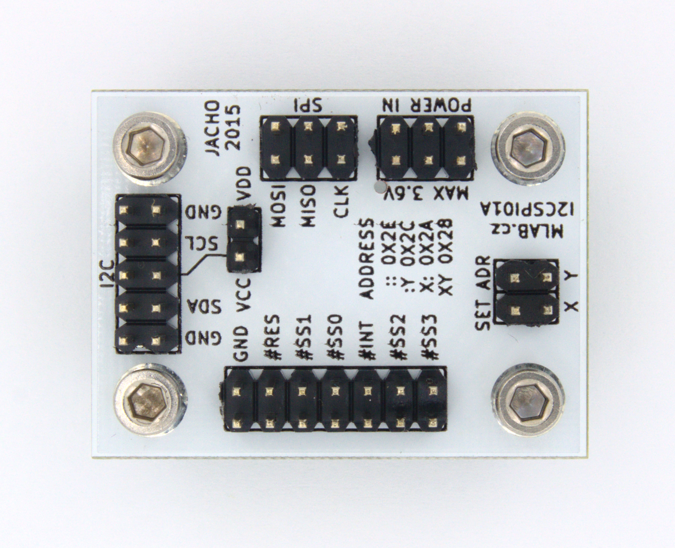
The I2CSPI01 module is designed for systems where a microcontroller with only an I2C interface needs to communicate with one or more SPI peripherals. It acts as a bridge that translates I2C commands into SPI signals, allowing integration of SPI devices such as ADCs, DACs, memory chips, or sensors into an I2C-based architecture. This simplifies wiring and reduces the number of required signals.
| Parameter | Value |
|---|---|
| Power Supply | Max. 3.6 V |
| Dimensions | 40.13 x 30.00 x 16 mm |
| Interface | I2C (up to 400 kHz), SPI (up to 1.843 MHz) |
| IC Used | SC18IS602B |
| Qty | Value | Footprint | References |
|---|---|---|---|
| 5 | 10k | SMD_Packages:SMD-0805 | R1, R2, R4, R6, R7 |
| 4 | _ | Dira:MountingHole_3mm | P1, P2, P3, P4 |
| 3 | CONN_2 | Hrebinky:Pin_Header_Straight_1x02 | J5, J6, J7 |
| 1 | - | SMD_Packages:SMD-0805 | R5 |
| 1 | 0R | SMD_Packages:SMD-0805 | R3 |
| 1 | 100nF | SMD_Packages:SMD-0805 | C1 |
| 1 | 10uF | SMD_Packages:SMD-0805 | C2 |
| 1 | BZV55C-3,6V | MLAB_D:Diode-MiniMELF_Standard | D1 |
| 1 | JUMP_3X2 | Hrebinky:Pin_Header_Straight_2x03 | J4 |
| 1 | JUMP_3X2 | Pin_Header_Straight_1x03:Pin_Header_Straight_2x03 | J1 |
| 1 | JUMP_5X2 | Hrebinky:Pin_Header_Straight_2x05 | J2 |
| 1 | JUMP_7X2 | Hrebinky:Pin_Header_Straight_2x07 | J3 |
| 1 | SC18IS602B | SMD_Packages:TSSOP-16 | U1 |
It measures 30 × 40.1 mm and has 2 copper layers, 1.6 mm thick.
22 parts, built around the SC18IS602B. The full list of its parts is on this page, with links to each part's symbol and footprint where PCBKit's library has them.
From the mlab-modules/I2CSPI01 repository on GitHub, at the commit this page was made from: the board is hw/sch_pcb/I2CSPI01.kicad_pcb and its schematic hw/sch_pcb/I2CSPI01.kicad_sch. PCBKit opens the board in the browser, with nothing to install.
Its repository states no licence, so its author keeps all rights: ask mlab-modules before reusing the design.
xil-se/SX1257-PMOD
This is a PMOD built around the SX1257 transceiver. It uses an I2C-SPI bridge (SC18IS602B) since only 8 io pins are used.

ja1umi/MUTIF09Project
Various design materials for building my 8-bit-microprocessor-based single board computer(s)

meerstern/e-Paper_I2C_Module
e-Paper I2Cモジュールは[WAVESHARE製200x200, 1.54inch E-Inkディスプレイ][0]を搭載したモジュールです。 [WAVESHARE製200x200, 1.54inch E-Inkディスプレイ][0]はSPI接続ですが、 配線の容易性を実現するために[SPI I2CプロトコルブリッジIC SC18IS602B][1]を搭載してI2C化しています。…


VoronDesign/Voron-Hardware
Cool Hardware designed by the Voron Design group

hoglet67/RGBtoHDMI
Bare-metal Raspberry Pi project that provides pixel-perfect sampling of Retro Computer RGB/YUV video and conversion to HDMI

hackclub/OnBoard
💡 Join 1,000 teenagers and make your first PCB with a $100 grant!