2 layers66.9 × 74.5 mm
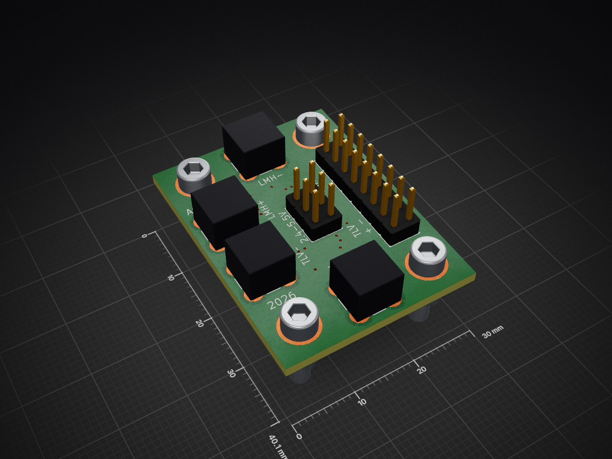
 mlab-modules/ACOMP01
Fast analog comparator module
ACOMP01 is an open-source printed circuit board by mlab-modules, from the mlab-modules/ACOMP01 repository on GitHub, published under the GPL-3.0 licence. It is a 2-layer board of 30 × 40.1 mm with 20 parts on 10 nets, routed with 90 tracks and 18 vias.
Its parts include 7 connectors, 4 capacitors, 2 resistors, 2 ICs and 1 diode.
The ACOMP01 module is a high-speed dual comparator board with differential LVDS outputs. It is designed for fast signal discrimination in nanosecond-scale timing systems. Each comparator features coaxial MCX input connectors and differential output for integration into high-speed digital acquisition or timing logic circuits.
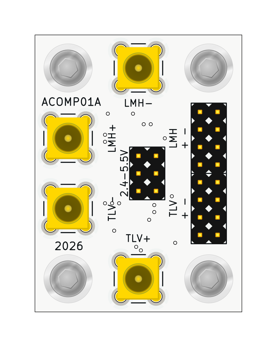
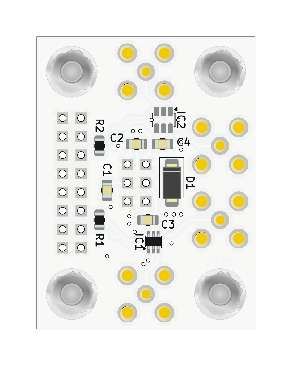
The module uses (2.4 V to 5.5 V) for the two comparators. Ensure proper voltages are applied as per the comparator requirements.
All inputs are via MCX connectors with ground-referenced shielding.
Each output is routed to a standard 3-pin header: OUT+, GND, OUT-
DNF (Do Not Fit) resistors R1 and R2 are placeholders for optional output termination.
| Qty | Value | Footprint | References |
|---|---|---|---|
| 4 | Conn_Coaxial | Mlab_CON:SMA6251A13G50 | J2, J3, J4, J5 |
| 2 | 100nF | Capacitor_SMD:C_0805_2012Metric | C3, C4 |
| 2 | DNF | Resistor_SMD:R_0805_2012Metric | R1, R2 |
| 2 | HEADER_2x04_PARALLEL | Mlab_Pin_Headers:Straight_2x04 | J6, J7 |
| 2 | HOLE | Mlab_Mechanical:MountingHole_3mm | M3, M4 |
| 2 | HOLE M3 | Mlab_Mechanical:MountingHole_3mm | M1, M2 |
| 1 | 10uF | Capacitor_SMD:C_0805_2012Metric | C1 |
| 1 | 1uF | Capacitor_SMD:C_0805_2012Metric | C2 |
| 1 | 2,4 - 5,5V | Mlab_Pin_Headers:Straight_2x03 | J1 |
| 1 | BZV55C-5,6V | Diode_SMD:D_SMA | D1 |
| 1 | LMH7220MK_NOPB | Package_TO_SOT_SMD:SOT-23-6 | IC2 |
| 1 | TLV3604DCKR | Package_TO_SOT_SMD:SOT-363_SC-70-6 | IC1 |
It measures 30 × 40.1 mm and has 2 copper layers, 1.6 mm thick.
20 parts. The full list of its parts is on this page, with links to each part's symbol and footprint where PCBKit's library has them.
From the mlab-modules/ACOMP01 repository on GitHub, at the commit this page was made from: the board is hw/sch_pcb/ACOMP01.kicad_pcb and its schematic hw/sch_pcb/ACOMP01.kicad_sch. PCBKit opens the board in the browser, with nothing to install.
Its repository publishes it under the GPL-3.0 licence: you may reuse it on that licence's terms (keep the author's notice, and for a copyleft licence share your changes alike).


atopile/atopile
Design circuit boards with code! ✨ Get software-like design reuse 🚀, validation, version control and collaboration in hardware; starting with electronics ⚡️

davidphilipbarr/Sweep
Sweep - a small promicro based keyboard inspired by the Ferris.

rusefi/rusefi
rusefi - GPL internal combustion engine control unit

hoglet67/RGBtoHDMI
Bare-metal Raspberry Pi project that provides pixel-perfect sampling of Retro Computer RGB/YUV video and conversion to HDMI

hackclub/OnBoard
💡 Join 1,000 teenagers and make your first PCB with a $100 grant!

FreeYourStream/freedeck-hardware
all the stuff you need to build your own FreeDeck