4 layers123.8 × 362.3 mm
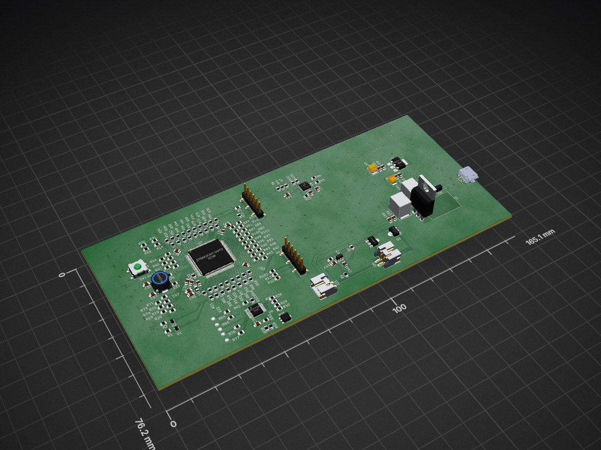
 mjbella/LED_Badge1
RGB LED Badge Prototype
LED Badge is an open-source printed circuit board by mjbella, from the mjbella/LED_Badge repository on GitHub. It is a 4-layer board of 165.1 × 76.2 mm with 400 parts on 606 nets, routed with 1,844 tracks and 314 vias.
It is built around the 74AHCT1G125SE, MTCH105-I/ST and L7805, with the MPU-6000 among its other parts. Its parts include 200 diodes, 107 resistors, 68 capacitors, 11 connectors and 8 ICs. It belongs with the lEDs and displays boards and the STM32 boards of this library.


This is a pcb badge with an MCU and tightly packed RGB LEDs (APA102).
| Qty | Value | Footprint | References |
|---|---|---|---|
| 200 | APA102 | gsg-modules:APA102-2020 | D1, D10, D11, D100, D101, D102, D103, D104, D105, D106, D107, D108, D109, D110, D111, D112 +184 |
| 96 | R | Resistors_SMD:R_0805 | R10, R11, R12, R13, R14, R16, R17, R18, R100, R101, R102, R103, R104, R105, R106, R107 +80 |
| 34 | C | Capacitors_SMD:C_0603 | C1, C2, C10, C11, C12, C13, C14, C15, C16, C17, C18, C19, C20, C21, C22, C23 +18 |
| 28 | C | Capacitors_SMD:C_0805 | C35, C36, C38, C39, C41, C42, C43, C44, C45, C46, C47, C48, C49, C50, C51, C52 +12 |
| 7 | R_Small | Resistors_SMD:R_0805 | R1, R2, R6, R7, R8, R9, R15 |
| 5 | TEST_1P | gsg-modules:TESTPOINT-50MIL | J29, J30, J31, J32, J33 |
| 3 | 0 | Resistors_SMD:R_0805 | R28, R33, R59 |
| 2 | 6.8p | Capacitors_SMD:C_0805 | C55, C57 |
| 2 | 74AHCT1G125 | TO_SOT_Packages_SMD:SOT-553 | U1, U2 |
| 2 | CP | Capacitors_Tantalum_SMD:CP_Tantalum_Case-B_EIA-3528-21_Reflow | C64, C67 |
| 2 | CP | Capacitors_Tantalum_SMD:CP_Tantalum_Case-E_EIA-7260-38_Reflow | C58, C61 |
| 2 | Conn_01x02 | Connectors_JST:JST_PH_S2B-PH-SM4-TB_02x2.00mm_Angled | J23, J25 |
| 2 | Conn_01x06 | Pin_Headers:Pin_Header_Straight_1x06_Pitch2.54mm_SMD_Pin1Left | J21, J24 |
| 2 | Q_NMOS_GDS | TO_SOT_Packages_SMD:SOT-89-3 | Q1, Q2 |
| 1 | 10k | Resistors_SMD:R_0805 | R3 |
| 1 | AZ1117-3.3 | TO_SOT_Packages_SMD:SOT-223-3_TabPin2 | U8 |
| 1 | Crystal | Crystals:Crystal_SMD_FOX_FE-2pin_7.5x5.0mm | Y1 |
| 1 | Ferrite_Bead | Inductors_SMD:L_0805 | L1 |
| 1 | GS3 | Connectors:GS3 | J28 |
| 1 | L7805 | TO_SOT_Packages_THT:TO-220-3_Horizontal | U5 |
| 1 | MPU-6000 | badgelife:QFN-24_4x4mm_Pitch0.5mm_roundish | U4 |
| 1 | MTCH105 | Housings_SSOP:TSSOP-14_4.4x5mm_Pitch0.65mm | U6 |
| 1 | POT | Potentiometers:Potentiometer_Trimmer-EVM3S_R | RV1 |
| 1 | S-8252_(SOT23) | TO_SOT_Packages_SMD:SOT-23-6 | U3 |
| 1 | STM32F407VGTx | Housings_QFP:LQFP-100_14x14mm_Pitch0.5mm | U7 |
| 1 | SW_Push | Buttons_Switches_SMD:SW_SPST_B3SL-1002P | SW1 |
| 1 | USB_OTG | Connectors_USB:USB_Micro-B_Molex-105017-0001 | J22 |


keeos-io/ogham
Ogham — a dual-voice bytebeat synthesizer for Eurorack. Firmware (MIT) and hardware (CC BY-SA 4.0).

dennis9819/split-flap-controller
Sourcecode and Schematics for the controller of my split-flap display


It measures 165.1 × 76.2 mm and has 4 copper layers, 1.6 mm thick.
400 parts, built around the 74AHCT1G125SE, MTCH105-I/ST, L7805 and MPU-6000. The full list of its parts is on this page, with links to each part's symbol and footprint where PCBKit's library has them.
From the mjbella/LED_Badge repository on GitHub, at the commit this page was made from: the board is ledbadge.kicad_pcb. PCBKit opens the board in the browser, with nothing to install.
Its repository states no licence, so its author keeps all rights: ask mjbella before reusing the design.