4 layers44.5 × 34.9 mm
Eclair
upbeatcarri/eclair
Pocket device for taking quick notes, acting as a USB keyboard for PC sync etc., with custom apps samd21, tinygo
56 parts25

 mitsake/rng-pcb5
A hardware random number generator that uses avalanche noise. Based on the Trinket M0.
Rng pcb is an open-source printed circuit board by mitsake, from the mitsake/rng-pcb repository on GitHub, published under the CC-BY-SA-4.0 licence. It is a 2-layer board of 54.6 × 68 mm with 46 parts on 44 nets, routed with 169 tracks and 26 vias.
It is built around the ATSAMD21E18A-AF, AP2112K-3.3 and MMBT3904. Its parts include 10 capacitors, 6 resistors, 6 connectors, 3 ICs and 3 transistors. It belongs with the SAM D and SAM boards of this library.


This is my contribution to the Boldport Club's community run Board Swap Project, a hardware random number generator that uses avalanche noise to make patterns and roll dice. Apart from being part of the community project, my other motivations were interest in randomness and the processes that can be used to generate it, along with the idea of using PCBs to build an enclosure.
Please note that I made this for fun - if you need random numbers for anything important, this isn't the project you're looking for.
A ST662 charge pump produces the 12 V required to reverse-bias Q1, which produces the actual randomness. When electrons travel through this junction, Q2 allows current to flow to ground. This signal is amplified by Q3, run through a voltage divider, and fed into the ADC of an ATSAMD21E18 microcontroller, which has been flashed with the Adafruit Trinket M0 bootloader to allow programming with CircuitPython.
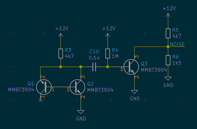
The display is an inexpensive 128 × 32 SSD1306-based OLED, and the in-built capacitive touch that's on the Trinket M0 hardware is routed to the top left (pin A3) and right (A4) corners of the top PCB to allow for input. If you don't have KiCad, you can use the PDF schematic - it's all pretty simple.
You can use the KiCad files in the 'hardware' directory to generate gerbers and get them made at your favourite PCB fab. I had my prototypes made at OSH Park (who accept the .kicad_pcb file directly), and once I'd finished the final design, got a 'protopack' made at Dirty PCBs. The gerbers are available in a zip file which should be accepted by most fabs, and assembly instructions can be found here. Make sure the PCB thickness is 1.6 mm - Dirty PCBs default to 1.2 mm, which will cause clearance issues.
This project was only possible thanks to the electrical designs, libraries, and articles written by others. Many thanks to the people below whose work was used to build this project, and to the Boldport Club Discord for the inspiration to build something and the help and support they're always happy to provide.
triangle_pattern.kicad_mod) is made with Quinn Rohlf's Trianglify library.mouse-bite-2mm-slot.kicad_mod footprint comes from this repository by madworm.| Qty | Value | Footprint | References |
|---|---|---|---|
| 6 | VAL** | rng-pcb:mouse-bite-2mm-slot | mouse-bite-2mm-slot, mouse-bite-2mm-slot, mouse-bite-2mm-slot, mouse-bite-2mm-slot, mouse-bite-2mm-slot, mouse-bite-2mm-slot |
| 4 | 0.1u | Capacitors_SMD:C_0603 | C4, C5, C8, C10 |
| 4 | 4k7 | Resistors_SMD:R_0603 | R1, R2, R3, R5 |
| 4 | Conn_01x01_Male | rng-pcb:TH_Pad | J3, J4, J5, J6 |
| 3 | MMBT3904 | Package_TO_SOT_SMD:SOT-416 | Q1, Q2, Q3 |
| 2 | 0.22u | Capacitors_SMD:C_0603 | C2, C3 |
| 2 | 10u | Capacitors_SMD:C_0603 | C1, C7 |
| 2 | 1u | Capacitors_SMD:C_0603 | C6, C9 |
| 2 | TestPoint | Connectors_TestPoints:Test_Point_Pad_d1.0mm | TP1, TP2 |
| 1 | 1M | Resistors_SMD:R_0603 | R4 |
| 1 | 1k5 | Resistors_SMD:R_0603 | R6 |
| 1 | AP2112K-3.3 | TO_SOT_Packages_SMD:TSOT-23-5 | U1 |
| 1 | ATSAMD21E18A | Housings_QFP:TQFP-32_7x7mm_Pitch0.8mm | U3 |
| 1 | LOGO | rng-pcb:triangle_pattern | G*** |
| 1 | OLED | Connector_PinHeader_2.54mm:PinHeader_1x04_P2.54mm_Vertical | J2 |
| 1 | ST662A | Housings_SOIC:SOIC-8_3.9x4.9mm_Pitch1.27mm | U2 |
| 1 | SW_Push | rng-pcb:Wurth-434331013822 | SW1 |
| 1 | USB_B_Micro | rng-pcb:Molex-476420001 | J1 |
The 38 most common of 46 parts.
It measures 54.6 × 68 mm and has 2 copper layers, 1.6 mm thick.
46 parts, built around the ATSAMD21E18A-AF, AP2112K-3.3 and MMBT3904. The full list of its parts is on this page, with links to each part's symbol and footprint where PCBKit's library has them.
From the mitsake/rng-pcb repository on GitHub, at the commit this page was made from: the board is hardware/rng-pcb.kicad_pcb. PCBKit opens the board in the browser, with nothing to install.
Its repository publishes it under the CC-BY-SA-4.0 licence: you may reuse it on that licence's terms (keep the author's notice, and for a copyleft licence share your changes alike).
upbeatcarri/eclair
Pocket device for taking quick notes, acting as a USB keyboard for PC sync etc., with custom apps samd21, tinygo


electricui/electricui-helloboard
Cute arduino compatible development board for introducing people to Electric UI

Hugoyhu/corgikeychain
Corgi "keychain" LilyPad with ATSAMD21E18

Hugoyhu/Hack-Club-Sticker-Development-Boards
"Sticker" dev boards.


OpenSiPM/sipm-bias-control
Single channel silicon photomultipliers for high-speed fluorescence imaging

M0LTE/pi-transceiver
An attempt to build a complete ham radio transceiver around a Raspberry Pi