4 layers100 × 100 mm
Pi TX 35W PA
M0LTE/pi-transceiver
An attempt to build a complete ham radio transceiver around a Raspberry Pi
161 parts15
 electricui/electricui-helloboard1
Cute arduino compatible development board for introducing people to Electric UI
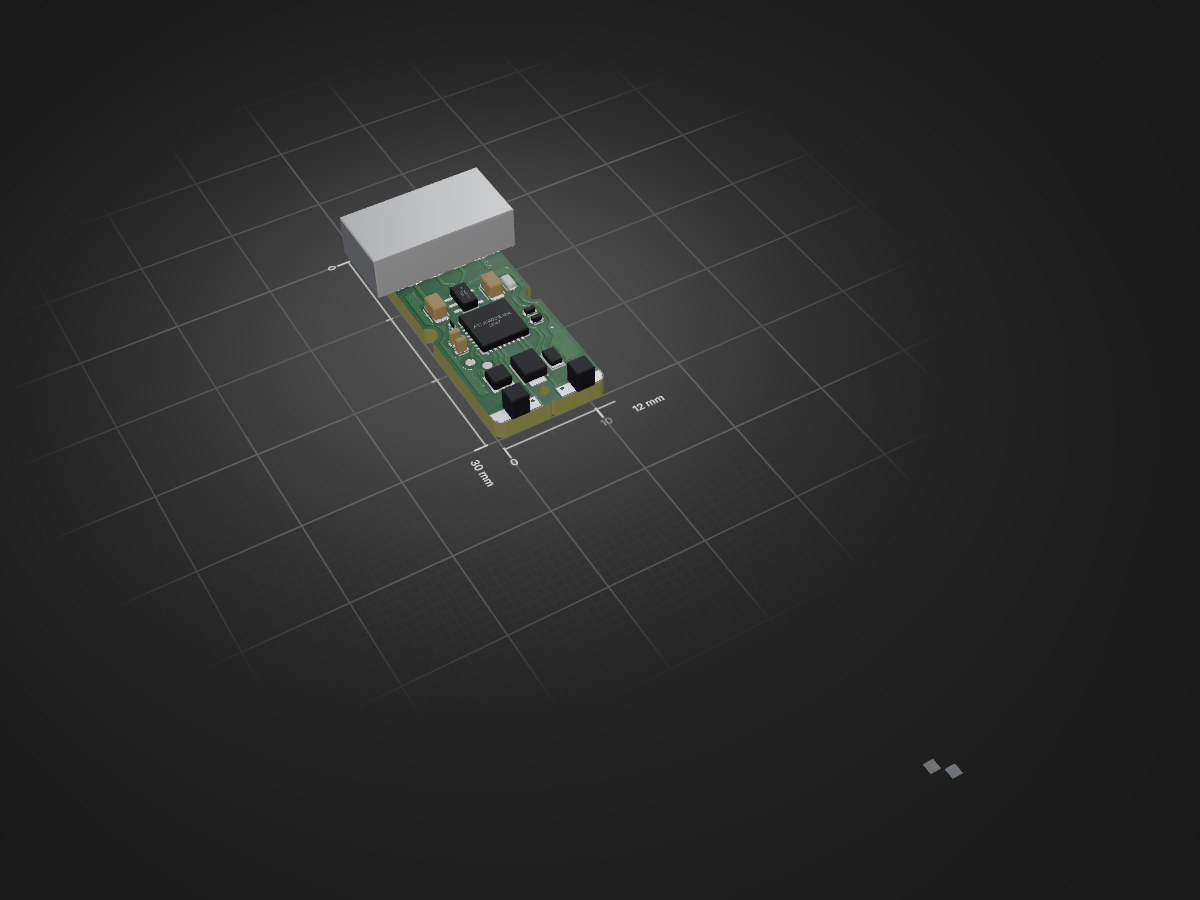
Electric greetings is an open-source printed circuit board by electricui, from the electricui/electricui-helloboard repository on GitHub. It is a 2-layer board of 12 × 30 mm with 19 parts on 35 nets, routed with 146 tracks and 14 vias.
It is built around the ATSAMD21E18A-AF, AP2112K-3.3 and APA102-2020. Its parts include 4 capacitors, 3 ICs, 2 resistors, 2 connectors and 1 diode. It belongs with the microcontroller boards boards and the SAM D and SAM boards of this library.


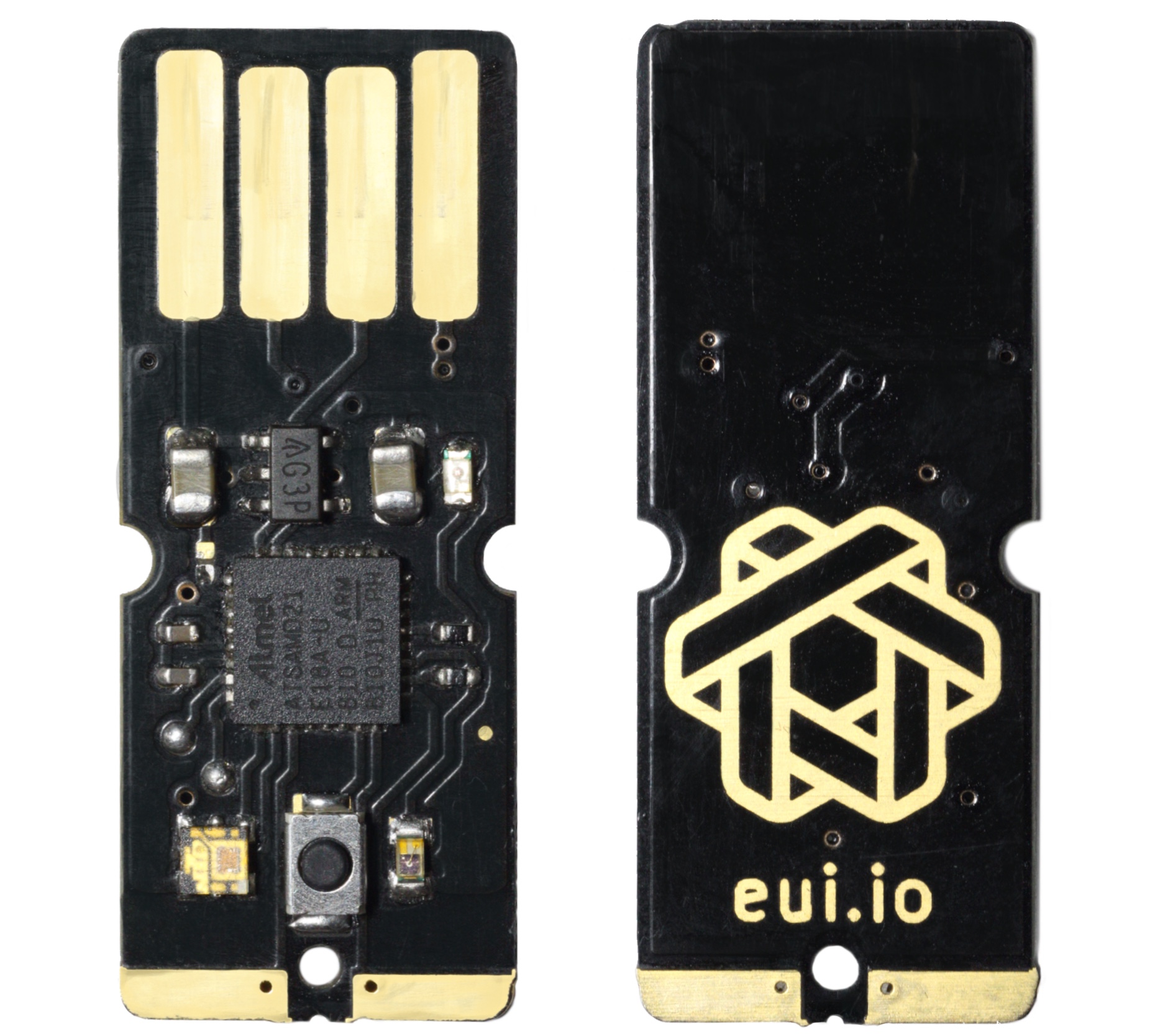
This is a tiny USB based evaluation board which makes development against a common platform easier, and helps introduce new users to Electric UI who may not have hardware on hand.
The board is based on the Atmel SAMD21E18 microcontroller, a neat little ARM Cortex M0 core in a compact 32 pin package.
The main goal of the board is to provide a quick and painless development experience to people who might not have played with embedded hardware before.
By including a few interactive components, and leveraging existing supported designs and software, the process should be as user-friendly as possible with no additional hardware/software modifications.
The board is very closely related to the Adafruit Trinket M0 design, but uses an insertable male USB footprint rather than rely on a USB micro cable. The KiCAD design files, gerbers and PDF's are in /hardware.
It includes an ambient light sensor, click button, two capacitive touch pads, and a APA102-2020 RGB LED for the user to interact with, discarding the USB micro connector and some power supply related components on the Trinket.
The micro-controller is suitably capable for it's footprint:
The small 'thumb-drive' form factor is intended to make the sticks easy to carry and give away.
The /firmware directory has a series of Arduino sketches which provide base examples for interacting with the hardware.
Most basic and intermediate example sketches in the electricui-embedded corpus should be directly compatible without modification.
The Adafruit M0 bootloader is used on this board, which supports the Arduino IDE through BOSSA, and will also enumerate as a USB mass storage device. Simply dropping any compatible UF2 file on the 'drive' will update the firmware.
The bootloader supports Arduino IDE flashing out of the box.
Install the SAMD and Adafruit SAMD hardware definitions from the Boards Manager, as described in this Adafruit guide.
Select Trinket M0 and the USB device in the Tools dropdown, then just flash the board as normal.
Note about Serial.print()
The Adafruit documentation is incorrect regarding usage of
SerialvsSerialUSB. This hardware does not requireSerialUSBto be used in sketches, as indicated in the Adapting Sketches to M0. That guide is relevant to other Atmel SAMD boards, but the Trinket just usesSerialby default.
Plug the USB stick into a compatible computer (Windows, macOS, Linux are all fine), and drop a UF2 file into the root of the TRINKETBOOT disk.
A SWD programmer is required to burn the boot-loader on new hardware for the first time, but can also be used to burn firmware as part of normal development. Doing this will save some memory normally used by the boot-loader.
While any other Atmel compatible SWD programmer (OpenOCD compatible, Atmel branded, or otherwise) can be used, I used a J-Link on Linux (Solus) to flash the boards for the first time. Programming wires are either soldered on or held in place (the two exposed round pads just above the RGB led), and the JLinkExe tool is used to burn the boot-loader binary as described in this thread (and below):
make BOARD=trinket_m0 on a *nix system./build/trinket_m0 folder, execute JLinkExe which I had installed in /opt/segger/jlink.si 1 to set the programming mode to SWD,speed 4000 to set programming speed to 4kHz,device ATSAMD21E18 for this target,loadbin bootloader-trinket_m0-v2.0.0-adafruit.9-2-g1e0d553.bin, 0x00000000 to burn the freshly built Trinket M0 bootloader to the base address 0x00000000.r to reset the device,g to run the program (though I'd advise just power cycling the target at this point),Makerfabs produced the boards, but any basic tier fab should work fine. 2.0mm thick FR4 is required to fit in normal sockets, and I'd recommend an ENIG finish as it looks a lot nicer.
The rest of the parts can be ordered from DigiKey or Adafruit (if you pull parts off existing Trinket M0 boards).
Assembly should be done with paste and hot air, or a reflow oven if possible. As this board has some fine pitch parts and 0402 components, its not the easiest board for a beginner to assemble.
I was able to assemble boards by hand without magnification, so people familiar with 0402 and 0.5mm pitch QFN parts shouldn't have too many issues.
| Qty | Value | Footprint | References |
|---|---|---|---|
| 2 | 10u_X7R_2012M | Applidyne_Capacitor:CAPC2012X110N | C3, C4 |
| 2 | 1u_X5R_1005M | Applidyne_Capacitor:CAPC1005X60N | C1, C2 |
| 2 | PAD_SOLDER_2mm | Applidyne_Connector:PAD_SOLDER_2mm | P1, P2 |
| 2 | PROBE_PAD | Applidyne_Test:TP100 | TEST1, TEST2 |
| 1 | 10K0_1005M | Applidyne_Resistor:RESC1005X40N | R2 |
| 1 | 1K5_1005M | Applidyne_Resistor:RESC1005X40N | R1 |
| 1 | ALS-PT19-315C | Applidyne_Special:TEMT7000X | Q1 |
| 1 | AP2112K-3.3 | Applidyne_SOT:SOT95P280X145-5L30L | U2 |
| 1 | APA102-2020 | Applidyne_LED:AP102_200X200X90L | U3 |
| 1 | ATSAMD21E18A | Applidyne_QFN:QFN33P50_500X500X100L40X24T345N | U1 |
| 1 | B3U-1000P_SPST-NO_SMD | Applidyne_Switch:B3U-1000P | SW1 |
| 1 | LED_RED_1608M | Applidyne_LED:LEDC1608X80L40L | D1 |
| 1 | LOGO | Applidyne_Logo:EUI_LOGO_1000X940_MASK | LOGO1 |
| 1 | SOLDER-LINK-2-TINY | Applidyne_Link:SJ1005-2N | SL1 |
| 1 | USB_A_MALE_PCB | Applidyne_USB:USB_A_PLUG_PCB | J?1 |
It measures 12 × 30 mm and has 2 copper layers, 2 mm thick.
19 parts, built around the ATSAMD21E18A-AF, AP2112K-3.3 and APA102-2020. The full list of its parts is on this page, with links to each part's symbol and footprint where PCBKit's library has them.
From the electricui/electricui-helloboard repository on GitHub, at the commit this page was made from: the board is hardware/electric-greetings/electric-greetings.kicad_pcb. PCBKit opens the board in the browser, with nothing to install.
Its repository states no licence, so its author keeps all rights: ask electricui before reusing the design.
M0LTE/pi-transceiver
An attempt to build a complete ham radio transceiver around a Raspberry Pi

upbeatcarri/eclair
Pocket device for taking quick notes, acting as a USB keyboard for PC sync etc., with custom apps samd21, tinygo


mitsake/rng-pcb
A hardware random number generator that uses avalanche noise. Based on the Trinket M0.

Hugoyhu/corgikeychain
Corgi "keychain" LilyPad with ATSAMD21E18

Hugoyhu/Hack-Club-Sticker-Development-Boards
"Sticker" dev boards.

