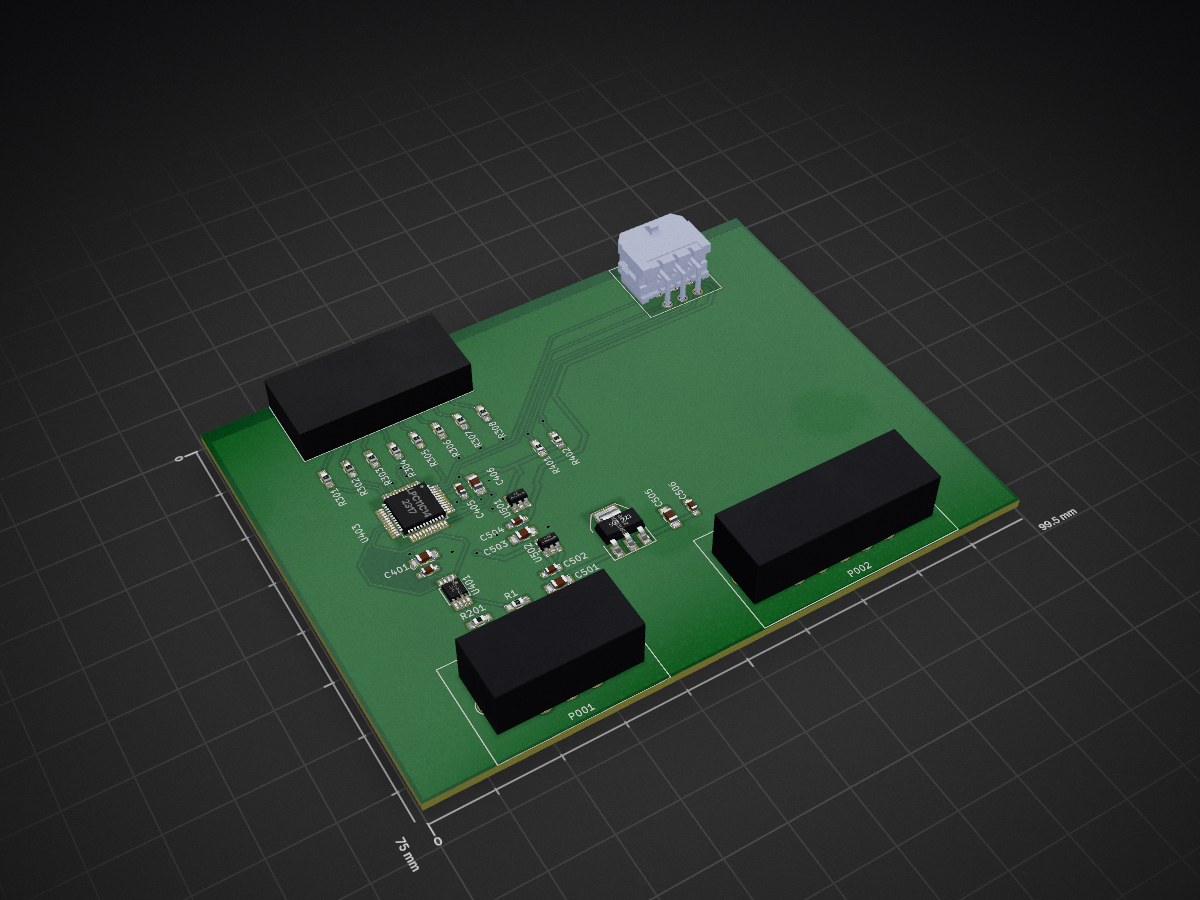
2 layers99.5 × 75 mm
 MITEVT/opel_driver_interface
MIT EVT's Opel GT Project Driver Interface Module. Acts as an inteface between the user and the electrical system for controlling power distribution and auxiliary peripherals.
Opel driver interface is an open-source printed circuit board by MITEVT, from the MITEVT/opel_driver_interface repository on GitHub, published under the MIT licence. It is a 2-layer board of 99.5 × 75 mm with 31 parts on 77 nets, routed with 278 tracks and 22 vias.
It is built around the MCP2551-I/SN and ZSR1000GTA. Its parts include 12 resistors, 10 capacitors, 5 ICs and 4 connectors. It belongs with the interfaces and adapters boards and the NXP (LPC, Kinetis, i.MX RT) boards of this library.


MIT EVT's Opel GT Project Driver Interface Module. Acts as an inteface between the user and the electrical system for controlling power distribution and auxiliary peripherals.
NXP LPC11C14 Cortex-M0 Microcontroller
Takes user input in the form of key switches, level toggles, and button presses to activate main power distribution system and control auxilairy peripherals such as lights.
| Qty | Value | Footprint | References |
|---|---|---|---|
| 8 | 100 | Resistors_SMD:R_0603_HandSoldering | R301, R302, R303, R304, R305, R306, R307, R308 |
| 3 | .1μ | Capacitors_SMD:C_0603_HandSoldering | C502, C504, C506 |
| 3 | 10μ | Capacitors_SMD:C_0805_HandSoldering | C501, C503, C505 |
| 2 | 0.1uF | Capacitors_SMD:C_0603_HandSoldering | C402, C405 |
| 2 | 10k | Resistors_SMD:R_0603_HandSoldering | R401, R402 |
| 2 | 10uF | Capacitors_SMD:C_0805_HandSoldering | C401, C406 |
| 1 | 20k | Resistors_SMD:R_0603_HandSoldering | R1 |
| 1 | CANCONNECTOR | MITEVT_AUTOMOTIVECON:776280-1 | P001 |
| 1 | CONN_01X14 | MITEVT_AUTOMOTIVECON:776267-1 | P002 |
| 1 | DEBUG_LED | Connectors_Molex:Connector_Microfit3_Header_02x08_Angled_43045-160x | P101 |
| 1 | ISP | Connectors_Molex:Connector_Microfit3_Header_02x03_Angled_43045-060x | P100 |
| 1 | LPC11C14 | Housings_QFP:LQFP-48_7x7mm_Pitch0.5mm | U403 |
| 1 | MCP1755-33 | Housings_SOT-23_SOT-143_TSOT-6:SOT-23-5 | U501 |
| 1 | MCP1755-5 | Housings_SOT-23_SOT-143_TSOT-6:SOT-23-5 | U502 |
| 1 | MCP2551-I/SN | Housings_SSOP:MSOP-8_3x3mm_Pitch0.65mm | U401 |
| 1 | R | Resistors_SMD:R_0603_HandSoldering | R201 |
| 1 | Zsr1000gta | TO_SOT_Packages_SMD:SOT-223 | U503 |
It measures 99.5 × 75 mm and has 2 copper layers, 1.6 mm thick.
31 parts, built around the MCP2551-I/SN and ZSR1000GTA. The full list of its parts is on this page, with links to each part's symbol and footprint where PCBKit's library has them.
From the MITEVT/opel_driver_interface repository on GitHub, at the commit this page was made from: the board is hardware/opel_driver_interface.kicad_pcb. PCBKit opens the board in the browser, with nothing to install.
Its repository publishes it under the MIT licence: you may reuse it on that licence's terms (keep the author's notice, and for a copyleft licence share your changes alike).

MITEVT/opel_velocity_interface
MIT EVT's Opel GT Project Driver Interface Module. Acts as an inteface between the user and the electrical system for controlling power distribution and auxiliary peripherals.


pggood/Megasquirt-MS3-Bootloader
Bootloader to initialise MS3 if you need to replace the HCS12


