2 layers52.2 × 52.2 mm
Base promicro
google/mozc-devices
Circuit diagrams and firmware source code for Gboard DIY keyboards
30 parts3kApache-2.0
 mikechristle/BitClock
A clock that displays the time in binary.
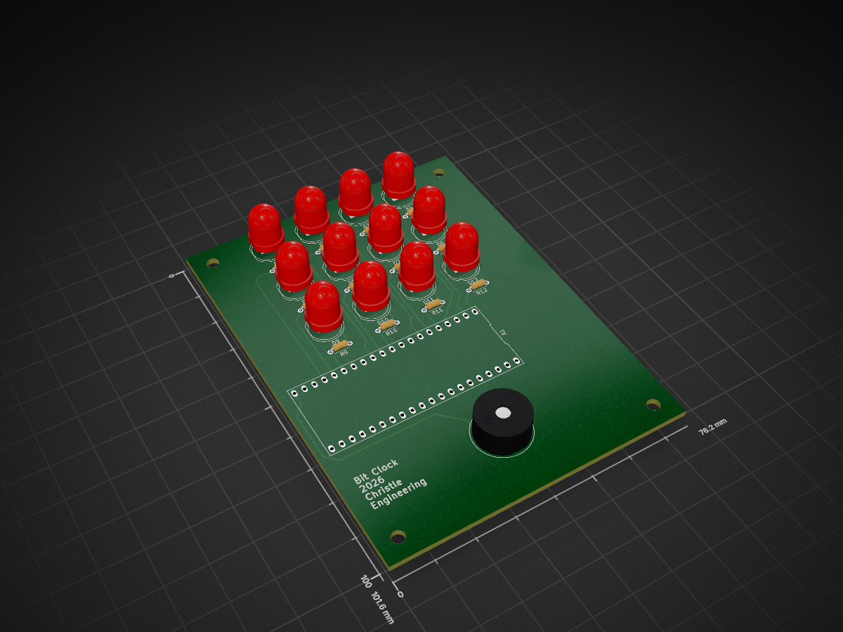
BitClock is an open-source printed circuit board by mikechristle, from the mikechristle/BitClock repository on GitHub, published under the MIT licence. It is a 2-layer board of 76.2 × 101.6 mm with 30 parts on 45 nets, routed with 64 tracks and 0 vias.
Its parts include 12 resistors and 12 diodes. It belongs with the lEDs and displays boards and the RP2040 boards of this library.
How can I display the time. Let me count the ways.
Over the years I have built several clock projects to display the time in interesting ways. Most have had limited success because of the challenge of keeping accurate time. This clock uses a Raspberry Pi Pico W to get the correct time over the internet. This is definitely overkill for a clock, but at $6 I said why not.
A clock that displays the time in binary.
The display has three rows of four LEDs. The top row displays the hour, 1 to 12. The middle row displays the tens of minutes, 0 to 5. The bottom row displays the ones of minutes, 0 to 9.
The clock has a buzzer to play a song for an alarm. To set the alarm time, use the PC Control Program.
The BitClock is controlled by a Raspberry Pi Pico W. All the code is written in Micro-Python. The code will get the current time over the internet using the get_ntp_time library.
The file network.info contains the login credentials for you router. When the clock powers up, it will use this info to login, then display the last byte of the IP address for 10 seconds. This address is needed in the PS control program to connect to the clock.
The control program was written in Python. It runs on a PC and communicates with the clock with a socket connection. I tested is on Windows, since it is Python it should run on Apple and Linux. This program will allow you to set the alarm, set the time zone, and adjust the LED brightness.
The PCB was designed in KiCad version 10.0.1. It is a two layer board. All of the symbol and footprints are included in the local definition files.
| Qty | Value | Footprint | References |
|---|---|---|---|
| 12 | 330 | BitClock:R_Axial_DIN0204_L3.6mm_D1.6mm_P5.08mm_Horizontal | R1, R2, R3, R4, R5, R6, R7, R8, R9, R10, R11, R12 |
| 12 | LED | BitClock:LED_D8.0mm | D1, D2, D3, D4, D5, D6, D7, D8, D9, D10, D11, D12 |
| 1 | Buzzer | BitClock:Buzzer_D14mm_H7mm_P10mm | BZ1 |
| 1 | RaspberryPi_Pico | BitClock:DIP-40_700_ELL | A1 |
The 26 most common of 30 parts.
It measures 76.2 × 101.6 mm and has 2 copper layers, 1.6 mm thick.
30 parts. The full list of its parts is on this page, with links to each part's symbol and footprint where PCBKit's library has them.
From the mikechristle/BitClock repository on GitHub, at the commit this page was made from: the board is PCB/BitClock.kicad_pcb and its schematic PCB/BitClock.kicad_sch. PCBKit opens the board in the browser, with nothing to install.
Its repository publishes it under the MIT licence: you may reuse it on that licence's terms (keep the author's notice, and for a copyleft licence share your changes alike).
google/mozc-devices
Circuit diagrams and firmware source code for Gboard DIY keyboards


VoronDesign/Voron-Hardware
Cool Hardware designed by the Voron Design group

hoglet67/RGBtoHDMI
Bare-metal Raspberry Pi project that provides pixel-perfect sampling of Retro Computer RGB/YUV video and conversion to HDMI

tenderlove/initial-v
It's a BMW shifter converted to a Bluetooth Keyboard that you use with Vim

hackclub/OnBoard
💡 Join 1,000 teenagers and make your first PCB with a $100 grant!

