

2 layers100 × 85 mm
 michpro/Arduino_LMeter_shield3
Arduino Inductance Meter shield
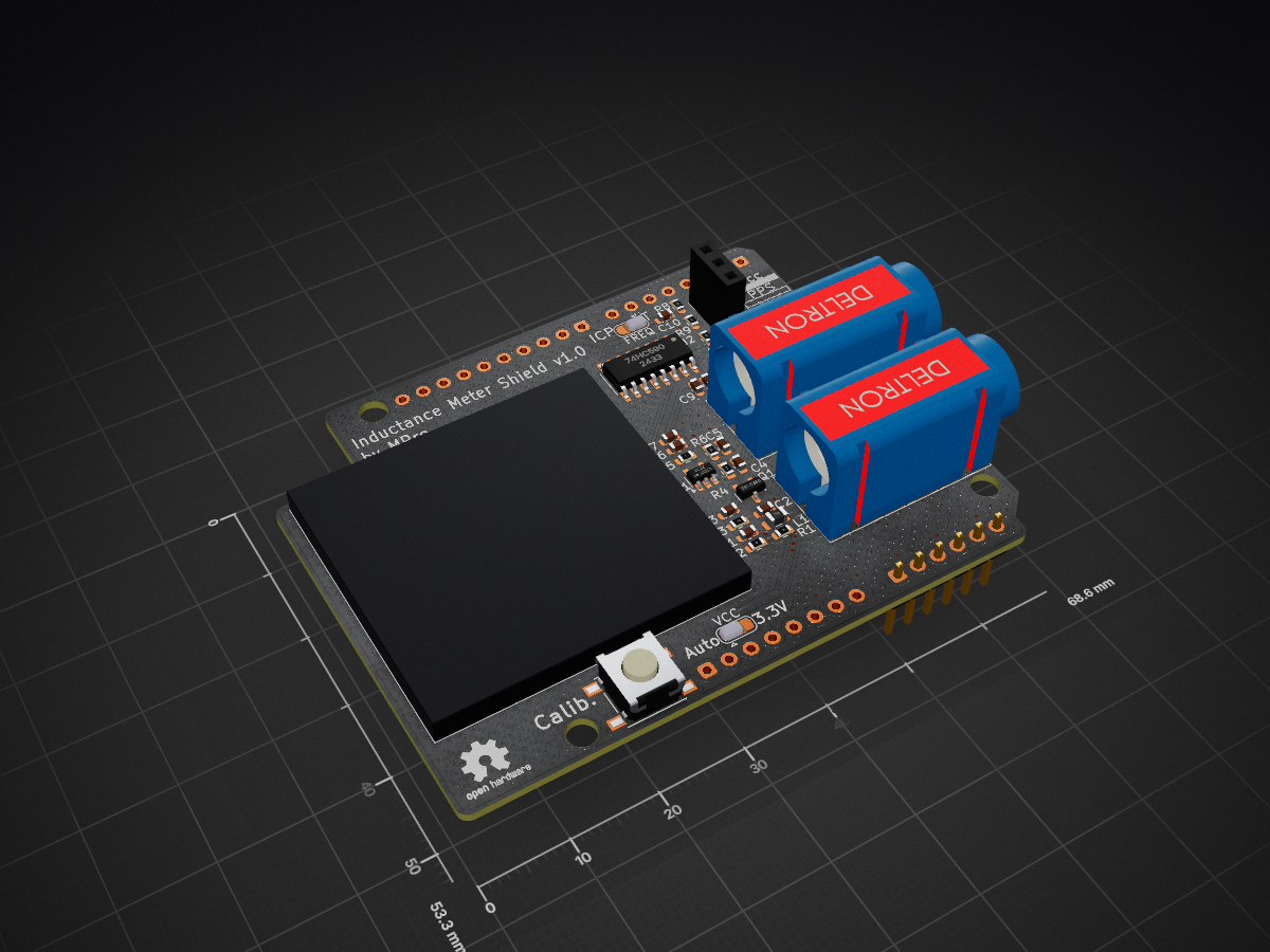
Arduino LMeter shield is an open-source printed circuit board by michpro, from the michpro/Arduino_LMeter_shield repository on GitHub, published under the CERN-OHL-P-2.0 licence. It is a 2-layer board of 68.6 × 53.3 mm with 33 parts on 48 nets, routed with 125 tracks and 45 vias.
It is built around the 74HC590D and 2SC3356. Its parts include 10 capacitors, 10 resistors, 3 connectors, 2 ICs and 1 transistor. It belongs with the microcontroller boards boards and the AVR (ATmega, ATtiny) boards of this library.
The Arduino UNO Inductance Measurement Shield is a dedicated peripheral board designed to enable precise inductance measurements, a functionality absent in most conventional digital multimeters (DMMs). While specialized LCR meters offer inductance measurement, they typically lack broader capabilities such as voltage or current measurement. This shield addresses this gap by providing a compact, integrated solution for inductance quantification via frequency-domain analysis.
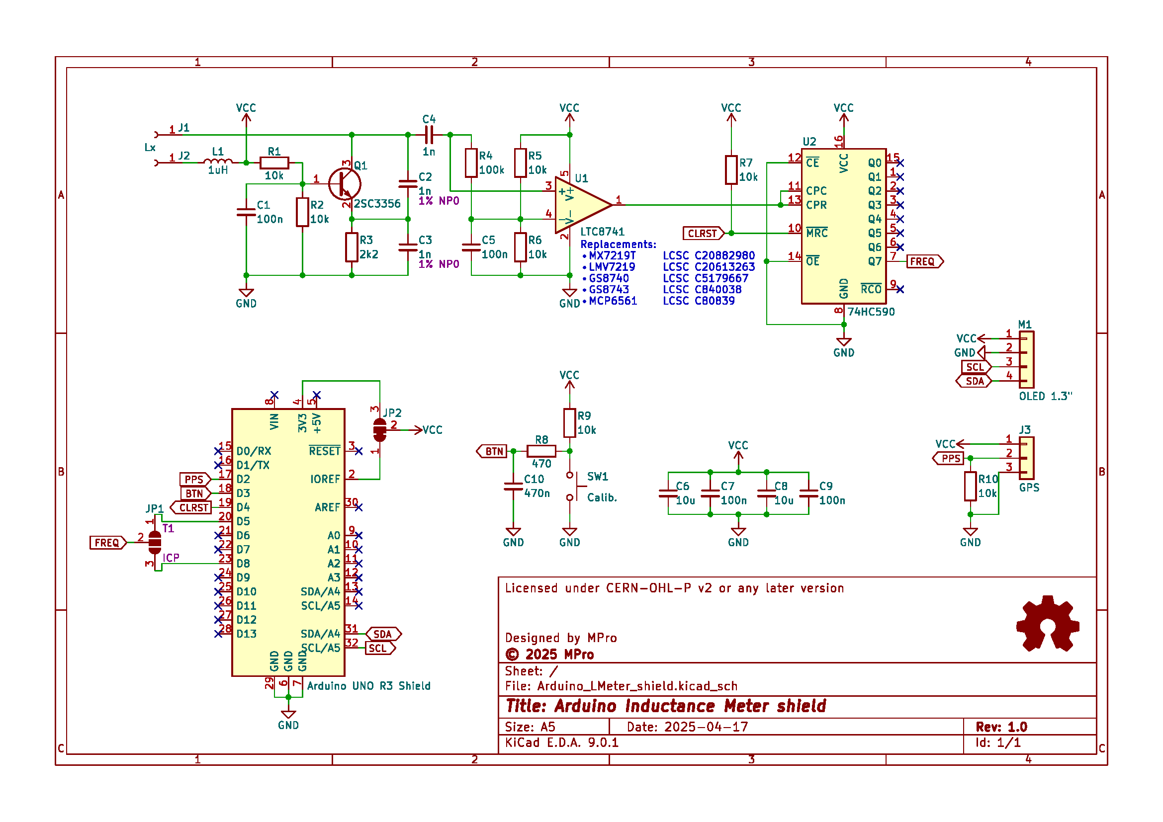
The shield employs a Colpitts oscillator topology modified to exclude the inductor. The unknown inductor (Lx) is connected externally via test leads, completing the resonant circuit.
Key design elements include:
An on-shield OLED displays measured inductance values in real time, eliminating external monitoring requirements.
(click on the image to see the 3D model)
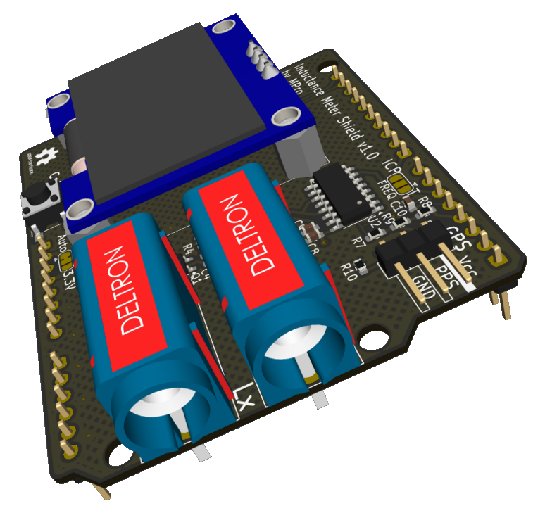
For Arduino UNO:
Interactive BOM and parts placement
The production files can be found in the location: https://github.com/michpro/Arduino_LMeter_shield/blob/master/production/
The software was developed in the Arduino environment (Source).
The running program can be in one of four defined states:
The Arduino calculates inductance using the resonant frequency (f) via the formula:
$\Large L_{x}=\frac{1}{(2\pi f)^2\cdot C_{total}}-L_{ref}$
Process Flow:
Displays the calculated Lx value on the OLED display.
If the measuring terminals are short-circuited without any additional inductance, pressing the ‘Calib’ button will cause the measured inductance value to be used to compensate for subsequent measurements (zeroing).
Copyright © 2025 Michal Protasowicki
Source: https://github.com/michpro/Arduino_LMeter_shield
Hardware part of this project is released under CERN Open Hardware Licence Version 2 - Permissive.

Source: https://github.com/michpro/Arduino_LMeter_shield/LMeter
Software part of this project is released under MIT Licence.

If You find my projects interesting and You wanted to support my work, You can give me a cup of coffee or a keg of beer :)
| Qty | Value | Footprint | References |
|---|---|---|---|
| 7 | 10k | footprints:R_0603_1608Metric | R1, R2, R5, R6, R7, R9, R10 |
| 4 | 100n | footprints:C_0603_1608Metric | C1, C5, C7, C9 |
| 3 | 1n | footprints:C_0603_1608Metric | C2, C3, C4 |
| 2 | 10u | footprints:C_0603_1608Metric | C6, C8 |
| 2 | Lx | footprints:4mm_Banana_Socket_Deltron_571 | J1, J2 |
| 1 | 100k | footprints:R_0603_1608Metric | R4 |
| 1 | 1uH | footprints:L_0805_2012Metric | L1 |
| 1 | 2SC3356 | footprints:SOT-23 | Q1 |
| 1 | 2k2 | footprints:R_0603_1608Metric | R3 |
| 1 | 470 | footprints:R_0603_1608Metric | R8 |
| 1 | 470n | footprints:C_0603_1608Metric | C10 |
| 1 | 74HC590 | footprints:SOIC-16_3.9x9.9mm_P1.27mm | U2 |
| 1 | Arduino UNO R3 Shield | footprints:Arduino_UNO_R3_WithMountingHoles_Profiled_no_SPI | A1 |
| 1 | Calib. | footprints:SW_Push_1P1T_NO_6x6mm | SW1 |
| 1 | FREQ | footprints:SolderJumper-3_P1.3mm_Open_RoundedPad1.0x1.5mm | JP1 |
| 1 | GPS | footprints:PinHeader_1x03_P2.54mm_Horizontal | J3 |
| 1 | LTC8741 | Package_TO_SOT_SMD:SOT-23-5 | U1 |
| 1 | Logo_Open_Hardware_Small | footprints:OSHW-Logo2_7.3x6mm_SilkScreen | LOGO1 |
| 1 | OLED 1.3" | footprints:LCD_OLED_128X64_1.3_I2C | M1 |
| 1 | VCC | footprints:SolderJumper-3_P1.3mm_Bridged12_RoundedPad1.0x1.5mm | JP2 |


profdc9/ActiveDifferentialProbe
A RF Differential Probe based on the 2SC3356 transistor


andykarpov/walkie-talkie
A custom pcb for the original project https://vrtp.ru/index.php?act=categories&CODE=article&article=3351

ngrabbs/ember
Open pvpanel.kicadpro with KiCad 10. The project contains the recovered schematic, routed PCB, project-local footprint libraries, and solar-module STEP model.

marian1911/Proyecto-CUBESAT-TRANSPODER-VHF-UHF
En este repositorio se guardan todos los archivos de desarrollo referidos a el diseño y fabricacion del trasnponder VHF/UHF

It measures 68.6 × 53.3 mm and has 2 copper layers, 1 mm thick.
33 parts, built around the 74HC590D and 2SC3356. The full list of its parts is on this page, with links to each part's symbol and footprint where PCBKit's library has them.
From the michpro/Arduino_LMeter_shield repository on GitHub, at the commit this page was made from: the board is Arduino_LMeter_shield.kicad_pcb and its schematic Arduino_LMeter_shield.kicad_sch. PCBKit opens the board in the browser, with nothing to install.
Its repository publishes it under the CERN-OHL-P-2.0 licence: you may reuse it on that licence's terms (keep the author's notice, and for a copyleft licence share your changes alike).