
2 layers68 × 40 mm
Stm32-io extend
hardenedlinux/cheap-pcb
Cheap PCB: Better understanding the current status of hardware supply chain
44 parts170CC0-1.0

STM32F103 microcontroller board designed in KiCad – schematic, PCB layout and fabrication files
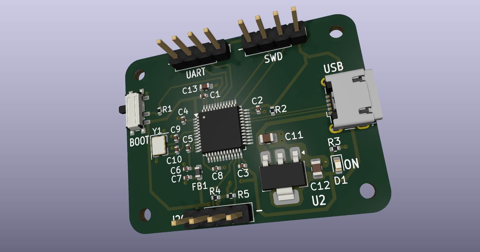
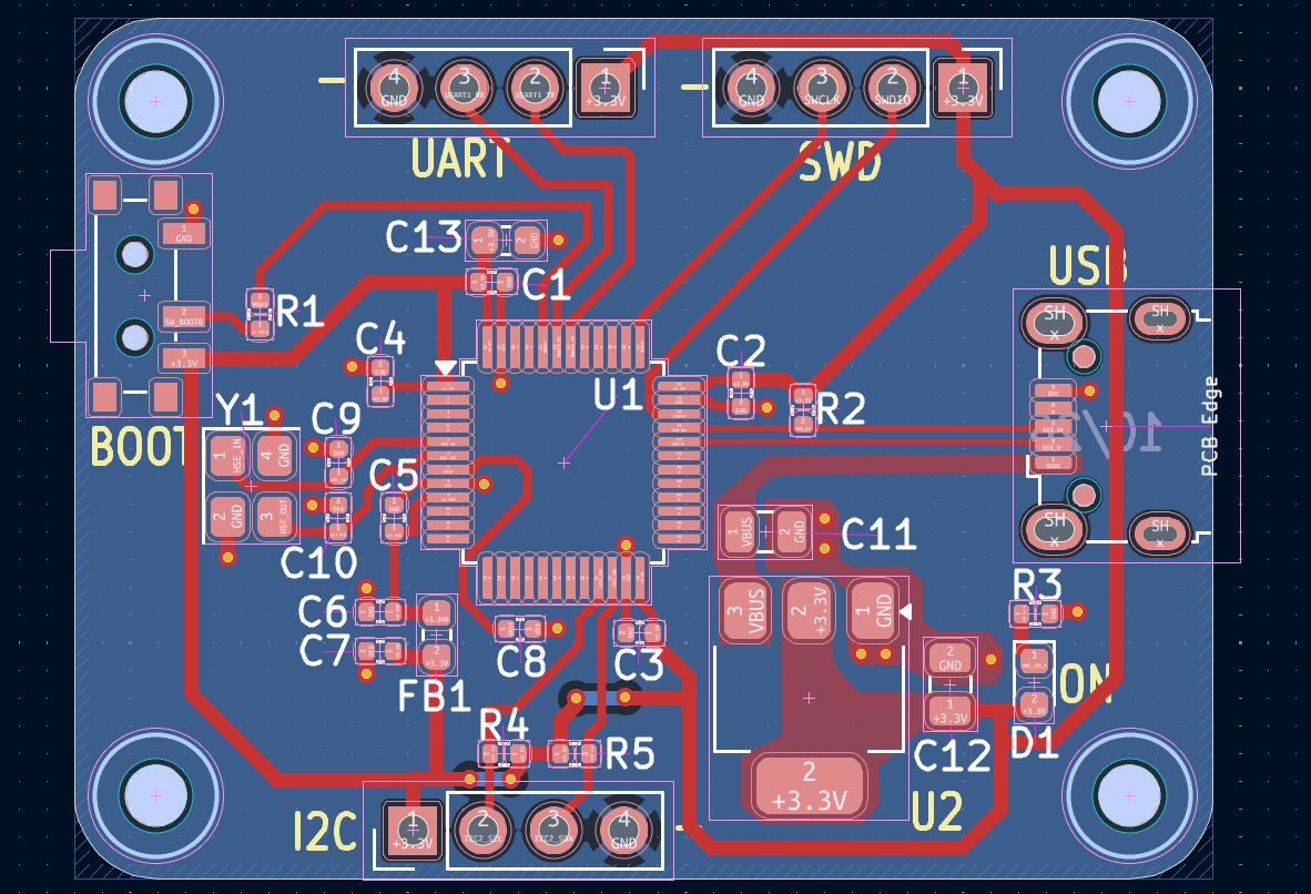
STM32 is an open-source printed circuit board by micahpinto, from the micahpinto/stm32-dev-board repository on GitHub, published under the MIT licence. It is a 2-layer board of 41 × 31 mm with 32 parts on 50 nets, routed with 213 tracks and 25 vias.
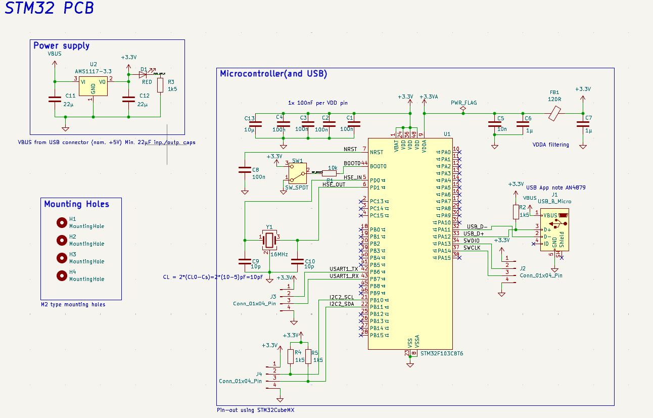
It is built around the STM32F103C8T6 and AMS1117-3.3. Its parts include 13 capacitors, 5 resistors, 4 connectors, 2 ICs and 1 diode. It belongs with the microcontroller boards boards and the STM32 boards of this library.


A compact 2-layer development board based on the STM32F103C8T6 microcontroller, designed in KiCad. Designed during my Master's as a hands-on project in microcontroller hardware and PCB design.
Status: Hardware design complete.
| Function | Pins |
|---|---|
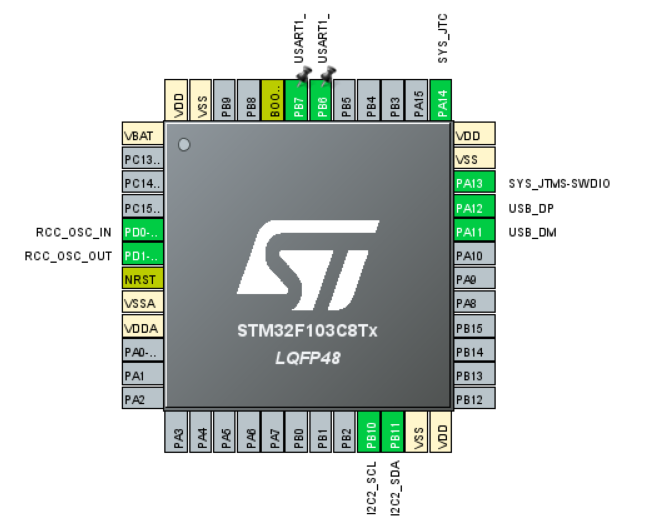
| SWD | PA13 (SWDIO), PA14 (SWCLK) |
| HSE crystal | PD0 (OSC_IN), PD1 (OSC_OUT) |
| USB | PA11 (D−), PA12 (D+) |
| USART1 | PB6 (TX), PB7 (RX) |
| I2C2 | PB10 (SCL), PB11 (SDA) |
| Folder | Contents |
|---|---|
Hardware/ | KiCad project, schematic, PCB and custom footprint library |
Firmware/stm32_pinout/ | STM32CubeMX pin configuration (stm32_pinout.ioc) |
Fabrication/ | Gerber files, drill file, BOM, placement file, schematic PDF |
images/ | Renders and screenshots |
| Qty | Value | Footprint | References |
|---|---|---|---|
| 5 | 100n | Capacitor_SMD:C_0402_1005Metric | C1, C2, C3, C4, C8 |
| 4 | 1k5 | Resistor_SMD:R_0402_1005Metric | R2, R3, R4, R5 |
| 4 | MountingHole | MountingHole:MountingHole_2.2mm_M2 | H1, H2, H3, H4 |
| 3 | Conn_01x04_Pin | Connector_PinHeader_2.54mm:PinHeader_1x04_P2.54mm_Vertical | J2, J3, J4 |
| 2 | 10p | Capacitor_SMD:C_0402_1005Metric | C9, C10 |
| 2 | 1µ | Capacitor_SMD:C_0402_1005Metric | C6, C7 |
| 2 | 22µ | Capacitor_SMD:C_0805_2012Metric | C11, C12 |
| 1 | 10k | Resistor_SMD:R_0402_1005Metric | R1 |
| 1 | 10n | Capacitor_SMD:C_0402_1005Metric | C5 |
| 1 | 10µ | Capacitor_SMD:C_0603_1608Metric | C13 |
| 1 | 120R | Inductor_SMD:L_0603_1608Metric | FB1 |
| 1 | 16MHz | Crystal:Crystal_SMD_3225-4Pin_3.2x2.5mm | Y1 |
| 1 | AMS1117-3.3 | Package_TO_SOT_SMD:SOT-223-3_TabPin2 | U2 |
| 1 | RED | LED_SMD:LED_0603_1608Metric | D1 |
| 1 | STM32F103C8T6 | Package_QFP:LQFP-48_7x7mm_P0.5mm | U1 |
| 1 | SW_SPDT | Library:SW_SPDT_PCM12 | SW1 |
| 1 | USB_B_Micro | Connector_USB:USB_Micro-B_Wuerth_629105150521 | J1 |
hardenedlinux/cheap-pcb
Cheap PCB: Better understanding the current status of hardware supply chain

milar111/HEAT
An open-source STM32 SMD assembly station for precision soldering. Uses a custom Smart Pulse & Coast algorithm to drive 400W mains heaters via SSR. Features OLED UI, NTC feedback, and safety cooling.


minhle4397/Line-Follower-Robot-v2
Improved Hardware and Firmware for Line Follower Robot

mupfdev/TrackMAG
An open hardware development board primarily intended for the development of accessible input devices.

RaduAndre/DeskMixer
DeskMixer is a software that allows control of application volumes with real sliders, and action mapping on buttons using arduino like platforms. The project was inspired originally by deej.

abda-s/STM32-Phill-s-Lab-PCB-Course
A beginner-friendly introduction to STM32 hardware design and KiCad

It measures 41 × 31 mm and has 2 copper layers, 1.6 mm thick.
32 parts, built around the STM32F103C8T6 and AMS1117-3.3. The full list of its parts is on this page, with links to each part's symbol and footprint where PCBKit's library has them.
From the micahpinto/stm32-dev-board repository on GitHub, at the commit this page was made from: the board is Hardware/STM32.kicad_pcb and its schematic Hardware/STM32.kicad_sch. PCBKit opens the board in the browser, with nothing to install.
Its repository publishes it under the MIT licence: you may reuse it on that licence's terms (keep the author's notice, and for a copyleft licence share your changes alike).