


2 layers110 × 84 mm
PKE
neriyashalom/PKE-Car-System
Final project - ESP32-S3 based PKE system for vehicle access and ignition
90 parts1
 MGlauser/Irin
The (holy) Watcher that never sleeps. Watching over your 12v battery system and integrates with HomeAssistant.
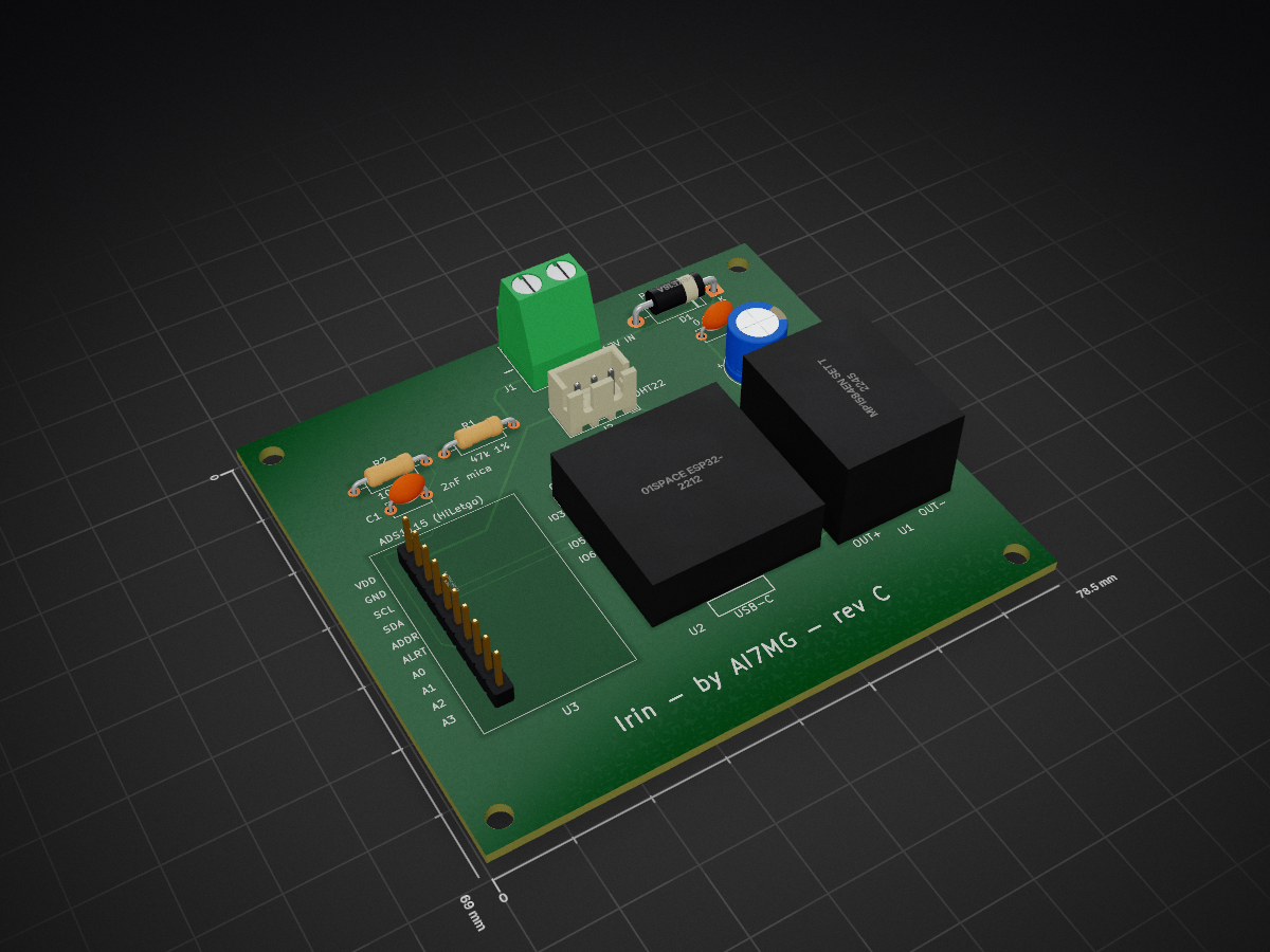
Irin is an open-source printed circuit board by MGlauser, from the MGlauser/Irin repository on GitHub, published under the MIT licence. It is a 2-layer board of 78.5 × 69 mm with 15 parts on 8 nets, routed with 44 tracks and 0 vias.
It is built around the DHT22, 100UF/35V and P6KE18A. Its parts include 3 capacitors, 3 ICs, 2 resistors, 2 connectors and 1 diode. It belongs with the power and home automation and IoT boards and the ESP32 and RISC-V boards of this library.
The wakeful one: an always-on battery watcher for Home Assistant.
Irin is an always-on battery monitor that clamps onto a battery's terminals and reports voltage, state of charge (SOC), charging activity and temperature to Home Assistant over WiFi, with a tiny OLED readout on the device itself.
The prototype watches the 12V accessory battery of a 2027 Subaru Uncharted GT (an EV whose 12V battery can run down in a couple of days of parking), but nothing in it is car-specific. Change a few lines of configuration and it monitors flooded lead-acid, AGM, LiFePO4 or sodium-ion batteries in 12V, 24V or 48V systems: RVs and boats, ham radio go-boxes and repeater power, solar and home backup banks, golf carts, stored vehicles.
No cloud, no vehicle telematics, no OBD dongle: one ESP32 board on the battery, one entry in your Home Assistant.
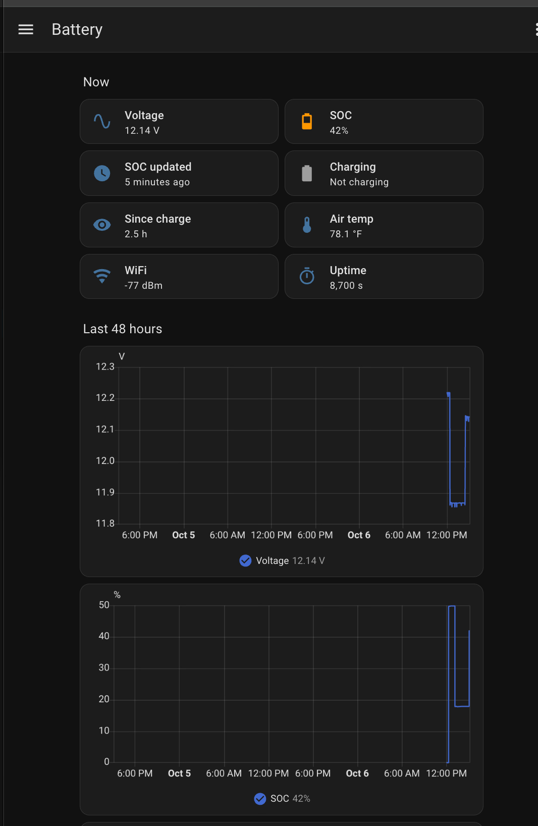
The included dashboard on the bench prototype. SOC steps only after a rest window (0% from an early reboot loop, then 50%, ~17% and 42% as the bench supply was changed); voltage is charted continuously. And 42% is, of course, the answer.
Irin (Aramaic עִירִין, ʿirin; singular ʿir) means "watchers", literally "the wakeful ones": those who do not sleep. It is the word for the Watchers of the Book of Enoch, whose first part (1 Enoch 1–36) is called The Book of the Watchers and survives in Aramaic among the Dead Sea Scrolls. The same word appears in Daniel 4:13: "a watcher and a holy one came down from heaven."
The name is meant in the sense of the holy Watchers, the ones who kept their post (1 Enoch 20 names them: Uriel, Raphael, Raguel, Michael, Saraqael, Gabriel and Remiel), not the fallen ones the book is better known for.
It is also the design in one word. Deep sleep was evaluated and rejected (on the prototype it would buy about 2% more runway), so the monitor stays awake around the clock, watching the battery so you don't have to.
| Voltage | Measured every 30 s with a 16-bit ADC (0.7 mV resolution at 12V) and published continuously, never gated. Charts charging cycles in detail. |
| State of charge | Looked up from resting voltage, temperature-corrected, and only updated when the battery has truly rested (see below). Holds its last good value otherwise, with a "last updated" timestamp. |
| Charging | On/off, detected from voltage with hysteresis, plus Time Since Charging. Shows whether the charging source (alternator, DC-DC converter, solar, shore power) is actually doing its job. |
| Away report | While Home Assistant is unreachable (the car is away from home WiFi, or HA is down), the device keeps a summary: lowest voltage, lowest SOC, time below the alert level, charging time and events. Published when it reconnects, e.g. "3.2 d: SOC min 46%, 4.0 h below 50%, 6 charges". Gaps under 30 minutes are ignored. |
| Temperature / humidity | DHT22 sensor, used for the SOC temperature correction. |
| On-device display | Voltage, SOC, temperature and rest/charging status on a 72×40 OLED. Blanks after 2 minutes to prevent burn-in; the BOOT button wakes it. Stays lit while charging. |
| Home Assistant | Native ESPHome integration (no MQTT broker), a ready-made dashboard, and history for long-term battery-health trends. Alerts are ordinary HA automations. |
It draws about 10 mA at 12V on WiFi, and about 40 mA while out of WiFi range with its fallback network up (see Fallback WiFi network).
A battery's voltage only tells you its state of charge when it has been sitting unloaded and uncharged for a while. During and after charging it reads high (surface charge), so a naive voltage-to-SOC lookup reports 100% on a battery that may be failing, and a low-battery alert fires late or never.
So SOC is recomputed only after the voltage has stayed below the charging threshold for 30 minutes and has been stable (within 5 mV per 5 minutes) for 15 minutes. Voltage itself is never gated: you always see the raw trace.
| Part | Notes |
|---|---|
| 01Space ESP32-C3-0.42LCD ("ESP32-C3 SuperMini 0.42 OLED") | ESP32-C3 with a built-in 72×40 SSD1306 OLED. I2C on SDA=GPIO5 / SCL=GPIO6 (verified). |
| ADS1115 16-bit ADC module (e.g. HiLetgo) | I2C at 0x48 (ADDR→GND), powered from 3.3V. Battery on A0 through the divider. |
| Voltage divider R1/R2, 1% metal film, same series | 47k / 10k for 12V systems (see the voltage table for 24/48V). |
| C1, 2 nF across R2 | 2× 1000 pF mica in parallel (low leakage). |
| MP1584EN buck module, set to 5.0V | Feeds the board's 5V pin. 12V systems only; see 24/48V below. |
| DHT22 / AM2302 + 3-pin JST-XH (J2) | Best outside the enclosure (cable ≤1 m at 3.3V); inside works, reading a few °C warm, which errs toward an early alert. |
| Fuse at the battery positive terminal | 5 A, DC-rated for the system voltage. Protects the wiring, not the 10 mA load. |
| TVS diode D1 | P6KE18A for 12V. Fitted as standard: it clamps switching transients, and a reversed hookup forward-biases it and blows the fuse. |
| Enclosure | 3D printed, PETG or ASA. |
PARTS.md.hardware/ (KiCad 10), PDF preview in
hardware/preview.pdf.hardware/breadboard/breadboard.html in a
browser. It is generated and checked against the schematic's netlist by
make_breadboard.py.R2 and C1 must return to the ADS1115's own GND pin, and that ground must meet power ground at exactly one point. If the divider and the ADC sit on different ground paths, the supply current's voltage drop appears in series with the measurement and gets multiplied by the divider ratio. On the prototype, 15 mV of ground drop between two breadboard rails became an 86 mV error at the battery, and it drifted. This applies to wired builds. On the PCB, the solid GND plane does the same job and R2/C1 connect to it directly.
The firmware is a single ESPHome config: esphome/irin.yaml.
With the Home Assistant ESPHome add-on (Device Builder):
python3 esphome/www/build_www.py (needs ESPHome installed; it writes
esphome/irin_www.js, the status page script), then copy the YAML and irin_www.js
into /config/esphome/. The script isn't in the repo because it is mostly ESPHome's
own page code.esphome/secrets.yaml.example to
the add-on's secrets.yaml (Secrets button in the add-on).Or with the ESPHome command line: copy secrets.yaml.example to secrets.yaml, fill
it in, and run esphome run irin.yaml.
Change device_name and friendly_name at the top of the YAML for each monitor you
build; entity IDs in HA follow friendly_name. The files in this repository are the
prototype's own configuration, named "Uncharted 12V", so the HA examples use entity IDs
like sensor.uncharted_12v_battery_voltage. If your friendly_name is "RV House", for
example, replace uncharted_12v with rv_house throughout ha_config/.
Every divider is different, so calibrate against a good meter:
calibrate_linear block and install. Battery Voltage
now shows the raw voltage at A0 (about 2 V on a 12V system).raw -> true, uncomment, and reinstall:
- calibrate_linear:
    - 2.00320 -> 11.500
- 2.61497 -> 15.000The fitted slope should land close to your measured (R1+R2)/R2. If it is off by more than a few tenths of a percent, suspect the ground wiring (see above) before the resistors.
uncharted_api_key from your secrets).sensor.garage_…). Rename them, or edit the dashboard to
match.ha_config/dashboard.yaml. For a
single card on an existing dashboard, use
ha_config/dashboard_card.yaml.ha_config/ (low SOC, charging
stalled, device offline). Tune thresholds against a week or two of your own data
before relying on them.Everything you need to change is in the substitutions: block at the top of
esphome/irin.yaml, plus the divider
resistors and calibration for other system voltages.
| Setting | What it does | 12V flooded default |
|---|---|---|
soc_table_v / soc_table_pct | Resting voltage → SOC lookup at 25 °C, ascending, same length | flooded table below |
charge_on_threshold | Above this: charging | 12.90 V |
charge_off_threshold | Below this: resting (the rest gate starts counting) | 12.80 V |
rest_required_sec | Time below charge_off_threshold before SOC updates | 1800 s |
stable_required_sec | Time the voltage must also be stable | 900 s |
slope_tolerance | Allowed drift per 5-minute tick to count as stable | 0.005 V |
temp_coeff | Resting-voltage temperature coefficient, V/°C, for the whole battery | 0.004 |
display_wake_ms | How long the OLED stays lit | 120000 |
ap_ssid | Name of the fallback WiFi network (see below). Don't name the vehicle: it broadcasts wherever you park | irin-Sunny |
soc_alert_pct | SOC alert level, used for the away report's "time below alert" (match your HA automation) | 50 |
away_min_sec | Shortest HA outage that counts as "away" and replaces the last report | 1800 s |
Rule for the charging thresholds: charge_off_threshold must sit above the
battery's full resting voltage (otherwise a full, idle battery looks like it is
charging), and below the lowest charging voltage you expect. Put
charge_on_threshold about 0.1 V higher (per 12V) for hysteresis.
When the device can't reach its WiFi for 90 seconds, it starts its own password-protected
network (ap_ssid). This is how you recover after changing your WiFi password without
re-flashing:
uncharted_fallback_password from your secrets.http://192.168.4.1). Pick your network and enter
the new password. The device saves it and reconnects.wifi_password in your secrets before the next firmware install. A
password saved this way only applies to the firmware that is running; any install with
a changed configuration goes back to the password in the YAML.Status page. The device also serves a small status page: voltage, SOC, temperature,
charging and the away report. When the device is out of WiFi range, join the fallback
network and open http://192.168.4.1. On your home network, use
http://<device_name>.local (e.g. http://uncharted-batt.local). Log in as irin, with
the fallback password. Useful when the battery is in a sealed box and the OLED is out of
reach. While the fallback network is up, the setup page is still what your phone's
network-login popup shows. If you need it in a browser, open any other address on the
device, or tap WiFi Setup on the status page, just above OTA Update. That link
appears only while the fallback network is up, because that is the only time the setup
page exists. It comes from esphome/irin_www.js, which is ESPHome's own status page
script with the link added; after upgrading ESPHome, regenerate it with
python3 esphome/www/build_www.py (using the ESPHome install that builds the firmware) and
copy it next to the YAML. Don't want the link? Replace js_include and js_url with
local: true and drop the file.
For a planned password change you don't need the fallback network at all: list both
passwords under wifi: networks: (same SSID), install over WiFi while the old one still
works, then change the router.
The cost: about 40 mA instead of 10 mA, but only while out of WiFi range. A device that can't find its network keeps the radio on, searching and broadcasting. On WiFi at home there is no extra draw. Measured on the prototype at 12V. The extra 30 mA is about 0.7 Ah a day, around 3% of the capacity between full and the 50% alert on a 50 Ah battery: for a car parked away from home, a few hours less warning out of several days. Daily trips cost about 0.25 Ah, which the drive home replaces.
To turn it off, for example on a battery bank that spends long periods out of range,
or if you'd rather not broadcast a network: delete the ap: block under wifi: and the
captive_portal: line, then install. The status page then only works on your home
network. To remove it as well, delete the web_server: block and the
web_server: {sorting_group_id: ...} lines. Out-of-range draw then falls to an estimated 20-30 mA
(not measured), not to 10 mA, because the radio keeps searching. The trade-offs:
wifi: reboot_timeout: 60min becomes active (ESPHome only uses it when there is no
fallback network): the device reboots after an hour without WiFi as a recovery
backstop. The away report survives it (kept in flash) and a full SOC rest window fits
between reboots, but the clock comes from Home Assistant, so after such a reboot,
charging while out of range isn't timestamped and Time Since Charging reads high
until the device is back home.Published voltage tables vary by manufacturer by ±0.05 V or more. If your battery's datasheet gives a resting-voltage curve, use it. The tables below are typical values: good starting points, not gospel.
soc_table_v:   "11.60, 11.75, 11.90, 12.02, 12.12, 12.22, 12.30, 12.38, 12.48, 12.58, 12.70"
soc_table_pct: "    0,    10,    20,    30,    40,    50,    60,    70,    80,    90,   100"
charge_on_threshold:  "12.90"
charge_off_threshold: "12.80"
temp_coeff: "0.004"
Alert at 50%: lead-acid cycle life drops sharply below 50% depth of discharge, and a partially discharged flooded battery sulfates. The temperature coefficient is the battery's open-circuit drift (~0.7 mV/°C per cell), not the 3-5 mV/°C/cell charger compensation figure. Using the charger figure over-corrects cold readings and suppresses winter alerts.
soc_table_v:   "11.60, 11.80, 11.95, 12.10, 12.25, 12.35, 12.45, 12.55, 12.65, 12.75, 12.85"
soc_table_pct: "    0,    10,    20,    30,    40,    50,    60,    70,    80,    90,   100"
charge_on_threshold:  "13.10"
charge_off_threshold: "13.00"
temp_coeff: "0.004"
AGM rests 0.10-0.15 V higher than flooded. Using the wrong table is the classic mistake: an AGM table on a flooded battery reads high and fires the 50% alert at roughly 35-40% actual SOC. Check the battery label. Alert at 50%.
soc_table_v:   "12.00, 12.90, 13.07, 13.13, 13.17, 13.20, 13.22, 13.25, 13.28, 13.30, 13.40"
soc_table_pct: "    0,    10,    20,    30,    40,    50,    60,    70,    80,    90,   100"
charge_on_threshold:  "13.60"
charge_off_threshold: "13.50"
temp_coeff: "0"
Read this before trusting LFP SOC. LiFePO4's resting voltage is almost flat: 20% to 90% spans only about 0.23 V, roughly 3 mV per percent, and the curve shifts with recent charge/discharge history and temperature. Voltage-based SOC is therefore only trustworthy near the ends of the curve (below ~20% and at full), and can be off by 10-20 points in the middle. Treat it as a low / OK / full indicator, and set the alert near 20%, where the curve bends and voltage becomes informative. LFP tolerates deep cycling far better than lead-acid anyway. Accurate mid-range LFP SOC needs current measurement (a shunt and coulomb counting), which this design does not do yet. The ADS1115 has spare inputs for exactly that; see Ideas below.
Also: a pack's BMS may disconnect the output at low charge. If the monitor is powered from the BMS-protected output, it goes dark exactly when the battery is lowest.
Sodium-ion cells have a sloped discharge curve, much more like lead-acid than LFP, so voltage-based SOC works well. Cell chemistries and pack configurations still vary between manufacturers, so there is no universal table. Build yours from the pack's datasheet discharge curve, or measure it (procedure below). Start with:
temp_coeff: "0"          # until you have characterized it
charge_off_threshold:    # just above the pack's full *resting* voltage
charge_on_threshold:     # charge_off_threshold + 0.1
Check the pack's maximum charge voltage. The 12V divider is designed for 16 V and is safe to about 20 V, so a pack that charges above ~15.5 V should get a slightly higher ratio, plus recalibration.
The measurement chain works the same at any voltage. Four parts change in hardware, and the per-12V numbers scale in firmware.
| 12V | 24V | 48V | |
|---|---|---|---|
| Design maximum (charging + margin) | 16 V | 32 V | 64 V |
| Divider R1 / R2 | 47k / 10k | 100k / 10k | 220k / 10k |
| Ratio | 5.7 : 1 | 11 : 1 | 23 : 1 |
| A0 at design maximum | 2.80 V | 2.91 V | 2.78 V |
| Input reaches the ADS1115's 3.6 V abs. max at | 20.6 V | 39.6 V | 82.8 V |
| Resolution at the battery | 0.7 mV | 1.4 mV | 2.9 mV |
| Buck converter input rating | MP1584EN (28 V max) OK | ≥ 60 V (24V lead-acid charges to ~29 V; the MP1584 is not OK) | ≥ 100 V |
| TVS | P6KE18A | P6KE36A (30.8 V standoff: skip it if you equalize above ~30.5 V) | SMBJ60A (60 V standoff): LFP 16S and lead-acid without equalization |
| Fuse | 32 V DC automotive blade OK | 32 V DC blade OK | 58 V DC-rated blade fuse; standard automotive blades are only 32 V |
| Calibration points | 11.5 V / 15.0 V | 23 V / 30 V | 46 V / 60 V |
Choosing parts for other cases:
Firmware for 24V / 48V: multiply every per-battery voltage by 2 (24V) or 4 (48V):
soc_table_v, both charging thresholds, slope_tolerance and temp_coeff. Lead-acid
and LFP tables scale exactly with cell count (a 12V lead-acid battery is 6 cells, 24V
is 12, 48V is 24; 12V LFP is 4S, 24V is 8S, 48V is 16S). Then calibrate as above. The
display and HA entities need no changes.
| Path | Contents | License |
|---|---|---|
esphome/ | ESPHome firmware config, secrets template, status page script (www/ builds it) | MIT |
ha_config/ | HA dashboard, draft automations, config snippets | MIT |
hardware/ | KiCad schematic, PCB placement, custom footprints, netlist, PDF preview | CERN-OHL-P-2.0 |
hardware/breadboard/ | Breadboard layout generator (Python) and its HTML output | MIT |
docs/images/ | Screenshots | MIT |
PARTS.md | Bill of materials, wiring, divider math | MIT |
CLAUDE.md | Full design record: rationale, measurements, rejected options, bench log. Written as context for the AI assistant used to develop the project, and the most detailed technical reference here. | MIT |
Bench-verified (October 2026): calibration within ±0.01 V from 11.5 to 16 V, the rest gate and temperature correction, the charging-detection hysteresis, the display timeout, and Home Assistant integration. Next: perfboard build, enclosure, in-vehicle data, then tuned alerts.
The firmware carries a version, irin_version at the top of
esphome/irin.yaml (currently 0.3.0). It shows in two places:
mglauser.irin plus the Irin version.When reporting a problem, include the Firmware line.
Rules for changes (semantic versioning, MAJOR.MINOR.PATCH):
| Change | Bump | Example |
|---|---|---|
| Fix that doesn't change what the device reports | PATCH | 0.3.0 → 0.3.1 |
| New feature or entity, changed behavior or default tunable | MINOR | 0.3.1 → 0.4.0 |
| Change that breaks existing installs (renamed entities, new required secret, new wiring) | MAJOR (MINOR while 0.x) |
irin_version in the same commit as the YAML change, add a line under
Changelog, and tag the commit: git tag v0.3.1 && git push --tags.irin-<car> with a WiFi Setup link on the status page, readable uptime, rest gate
requires a true 30 minutes of observed rest, Firmware sensor.hardware/ (except hardware/breadboard/):
CERN Open Hardware Licence v2, Permissive (CERN-OHL-P-2.0)Provided as-is. You are working on battery systems that can deliver very large currents. Fuse at the battery, insulate everything, and know your vehicle's service precautions.
| Qty | Value | Footprint | References |
|---|---|---|---|
| 4 | MountingHole_3.2mm_M3 | MountingHole:MountingHole_3.2mm_M3 | H1, H2, H3, H4 |
| 1 | 0.1uF | Capacitor_THT:C_Disc_D5.0mm_W2.5mm_P5.00mm | C3 |
| 1 | 01Space ESP32-C3-0.42LCD | Irin:ESP32C3_042LCD_2x8_P2.54mm_W17.78mm | U2 |
| 1 | 100uF/35V | Capacitor_THT:CP_Radial_D8.0mm_P3.50mm | C2 |
| 1 | 10k 1% | Resistor_THT:R_Axial_DIN0207_L6.3mm_D2.5mm_P10.16mm_Horizontal | R2 |
| 1 | 12V IN | TerminalBlock_Phoenix:TerminalBlock_Phoenix_MKDS-1,5-2-5.08_1x02_P5.08mm_Horizontal | J1 |
| 1 | 2nF mica | Capacitor_THT:C_Disc_D5.0mm_W2.5mm_P5.00mm | C1 |
| 1 | 47k 1% | Resistor_THT:R_Axial_DIN0207_L6.3mm_D2.5mm_P10.16mm_Horizontal | R1 |
| 1 | ADS1115 (HiLetgo) | Irin:ADS1115_HiLetgo_1x10_P2.54mm_W18mm_L28.3mm | U3 |
| 1 | DHT22 | Connector_JST:JST_XH_B3B-XH-A_1x03_P2.50mm_Vertical | J2 |
| 1 | MP1584EN set to 5.0V | Irin:MP1584EN_HW133_2x2Pad_P2.54mm_W10.16mm_L17.78mm | U1 |
| 1 | P6KE18A | Diode_THT:D_DO-15_P12.70mm_Horizontal | D1 |
It measures 78.5 × 69 mm and has 2 copper layers, 1.6 mm thick.
15 parts, built around the DHT22, 100UF/35V and P6KE18A. The full list of its parts is on this page, with links to each part's symbol and footprint where PCBKit's library has them.
From the MGlauser/Irin repository on GitHub, at the commit this page was made from: the board is hardware/irin.kicad_pcb and its schematic hardware/irin.kicad_sch. PCBKit opens the board in the browser, with nothing to install.
Its repository publishes it under the MIT licence: you may reuse it on that licence's terms (keep the author's notice, and for a copyleft licence share your changes alike).
neriyashalom/PKE-Car-System
Final project - ESP32-S3 based PKE system for vehicle access and ignition

Antozjr/Super-5-RTOS
Sistema CAN distribuido para un Renault 5 GTL (BCM + Gateway)

borislav968/s3mono
ЭСУД SECU-3 поддерживает использование регуляторов холостого хода на основе шагового привода или электромагнита (ШИМ).

jd710313/texecom-power-reset
A single board with an ESP32-C3 (Tasmota) and two on-board relays. It sits inside a Texecom Premier Elite 64-W housing and can remotely "hard power reset" the panel by briefly cutting both its battery and 16VAC feeds.

karolhof/ASV-PCBs
Actualizado el 05/10/2026 para KiCad 10. El esquema conserva cables continuos entre la alimentación, el ESP32, el LoRa y los dos conectores UART. Un punto marca una unión; un cruce sin punto no conecta.

mnorden81/RC-Multiswitch-ESP32-C3
CRSF Multiswitch 8 Kanaele, ESP32-C3 SuperMini, KiCad und Firmware

mnorden81/RC-Multiswitch-ESP32-S3
CRSF Multiswitch 8 Kanaele, ESP32-S3-Zero, KiCad und Firmware
