6 layers150 × 87 mm
POWERCORE V2.0 MOTHERBOARD
Rack-Robotics/Powercore-V2.0
Open-Source wire EDM power supply by Rack Robotics, Inc.
254 parts258
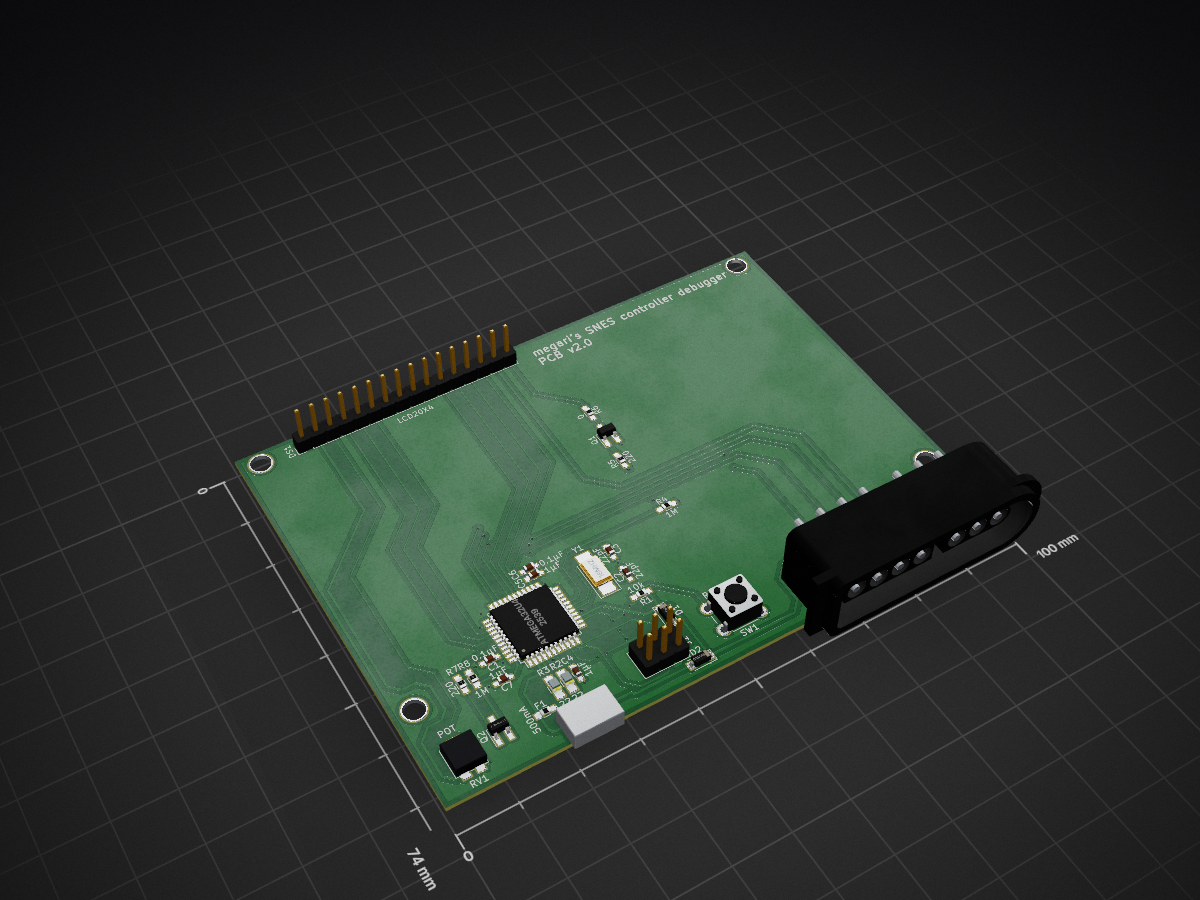
 megari/SNES_controller_debugger3
SNES controller debugger
SNES controller debugger 1 is an open-source printed circuit board by megari, from the megari/SNES_controller_debugger repository on GitHub. It is a 2-layer board of 100 × 74 mm with 32 parts on 35 nets, routed with 252 tracks and 37 vias.
It is built around the ATMEGA32U4, MBR0520 and DMG2302UK-7, with the DMP2215L-7-VB among its other parts. Its parts include 8 resistors, 7 capacitors, 3 connectors, 2 diodes and 2 transistors. It belongs with the retro computing and games and interfaces and adapters boards and the AVR (ATmega, ATtiny) boards of this library.


This is a little project for debugging SNES controllers. The PCB design files and the firmware source code are included.
The hardware uses an Atmel mega32u4 microcontroller.
The firmware uses the YAAL library and yaamake. These are included as submodules in the firmware/vendor directory.
The avr-gcc toolchain is required in order to compile the firmware. The repositories of your distribution probably have this available.
After the toolchain has been installed:
cd firmwareIf you haven't built yaamake yet, do so:
cd vendor/yaamake
make
cd ../..
Finally, build the firmware and program the board:
nano Makefile # Check that the programmer port is correct
make
make program| Qty | Value | Footprint | References |
|---|---|---|---|
| 4 | Megaris_fixed_footprints:MountingHole_3.4mm | H1, H2, H3, H4 | |
| 3 | 1µF | Capacitors_SMD:C_0603_HandSoldering | C4, C5, C7 |
| 2 | 0.1µF | Capacitors_SMD:C_0603_HandSoldering | C1, C6 |
| 2 | 1M | Resistors_SMD:R_0603_HandSoldering | R4, R8 |
| 2 | 22 | Resistors_SMD:R_0805_HandSoldering | R2, R3 |
| 2 | 220 | Resistors_SMD:R_0603_HandSoldering | R5, R7 |
| 2 | 22pF | Capacitors_SMD:C_0603_HandSoldering | C2, C3 |
| 2 | MBR0520 | Diodes_SMD:D_SOD-123 | D1, D2 |
| 1 | 0 | Resistors_SMD:R_0603_HandSoldering | R6 |
| 1 | 10k | Resistors_SMD:R_0603_HandSoldering | R1 |
| 1 | 16MHz | Crystals:Crystal_SMD_5032-2pin_5.0x3.2mm_HandSoldering | Y1 |
| 1 | 500mA | Resistors_SMD:R_0603_HandSoldering | F1 |
| 1 | ATmega32U4 | Housings_QFP:TQFP-44_10x10mm_Pitch0.8mm | U1 |
| 1 | Controller | SNES_Controller_Port:SNES_controller_port | J2 |
| 1 | DMG2302UK-7 | TO_SOT_Packages_SMD:SOT-23_Handsoldering | Q1 |
| 1 | DMP2215L-7 | TO_SOT_Packages_SMD:SOT-23_Handsoldering | Q2 |
| 1 | ICSP | Pin_Headers:Pin_Header_Straight_2x03_Pitch2.54mm | J1 |
| 1 | LCD20X4 | Megaris_fixed_footprints:LCD_2004_Pitch2.54mm | DS1 |
| 1 | MICRO_USB | Megaris_fixed_footprints:Conn_USBmicro-B_Amphenol_10118194-0001LF | J3 |
| 1 | POT | Megaris_fixed_footprints:Potentiometer_Trimmer_Vishay_TS53YL | RV1 |
| 1 | Reset | Buttons_Switches_THT:SW_PUSH_6mm | SW1 |
It measures 100 × 74 mm and has 2 copper layers, 0.8 mm thick.
32 parts, built around the ATMEGA32U4, MBR0520, DMG2302UK-7 and DMP2215L-7-VB. The full list of its parts is on this page, with links to each part's symbol and footprint where PCBKit's library has them.
From the megari/SNES_controller_debugger repository on GitHub, at the commit this page was made from: the board is kicad/SNES_controller_debugger_1.kicad_pcb. PCBKit opens the board in the browser, with nothing to install.
Its repository states no licence, so its author keeps all rights: ask megari before reusing the design.
Rack-Robotics/Powercore-V2.0
Open-Source wire EDM power supply by Rack Robotics, Inc.


a6-a9-ai/BLE-beacon-38x28mm-high-autonomy-CR2477
38x28mm BLE beacon optimized for high autonomy - can last up to years depending on use

Avinash1286/pendent
AURA: open wearable note-taking device development — PCB, printable case, firmware, Next.js/Convex notes, interactive 3D site and launch film.
