2 layers48.3 × 50.8 mm
Electronic load controller
ondras12345/electronic-load
Digital control for XHDZ-FZ-2g electronic load
63 parts2MIT

 mec-kon/weather_station3
A simple weather station hardware (pcb files) for recording temperature, humidity, pressure and airquality.
Weather station is an open-source printed circuit board by mec-kon, from the mec-kon/weather_station repository on GitHub, published under the GPL-3.0 licence. It is a 2-layer board of 24 × 57.8 mm with 73 parts on 57 nets, routed with 441 tracks and 40 vias.
It is built around the ESP-12F, BME280 and AMS1117-3.3, with the BAV99, BSS138 and BSS84 among its other parts. Its parts include 38 resistors, 10 capacitors, 8 diodes, 6 connectors and 5 ICs. It belongs with the home automation and IoT and sensors and measurement boards and the ESP8266 boards of this library.


A simple weather station hardware for recording temperature, humidity, pressure and airquality. The measured data can be provided over WiFi by using an ESP8266. This hardware is available as open source hardware and released under GPL-3.0 license.
This is a circuitboard based on an ESP8266 for reading and evaluating sensor data. By using an ESP8266, it is possible to evaluate sensor data directly and make it available via MQTT, for example. This makes it very easy to integrate the weather station into existing smart home systems such as OpenHAB, Home Assistant or ioBroker. Furthermore, the ESP8266 has an efficient low power mode, which allows battery operation or operation on a solar cell.
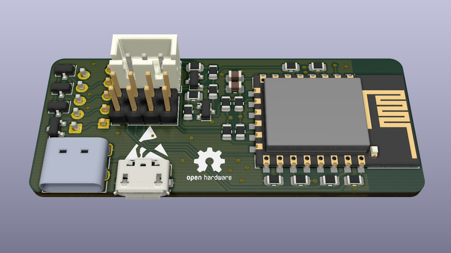
The board has six connection terminals. Three different for the power supply, two for the connection of external sensors and one for programming the ESP8266. The power can be supplied via micro-usb, usb-c or via a JST-XH plug. If the JST-XH connector is used, the capacity of a battery connected to the board can also be measured.
For temperature measurement, either an LM75 and a BME680 or BME280 can be used. If the air quality is to be measured as well, a BME680 needs to be used, otherwise a cheaper BME280 sensor is sufficient for temperature, air pressure and humidity.
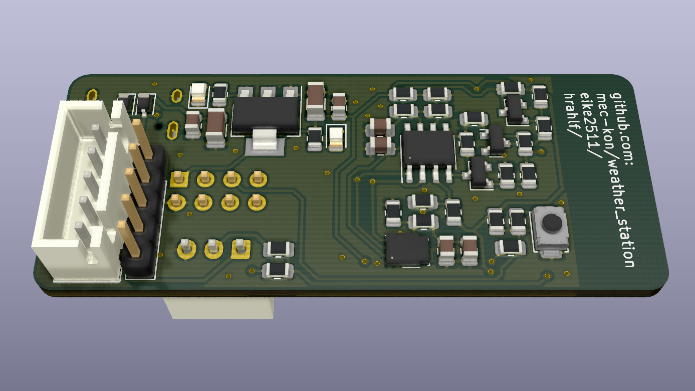
To wake up the ESP8266 from low power mode, the reset pin must be connected to GPIO16. On the board presented here this connection has already been made.
On the backside of the board a male pin header as well as a 5-pin JST-XH connector are located, to which further I2C devices or similar can be connected.
The ESP8266 can be programmed with an FTDI adapter. All needed pins can be found on the pin header on the front side. Example Software is provided here:
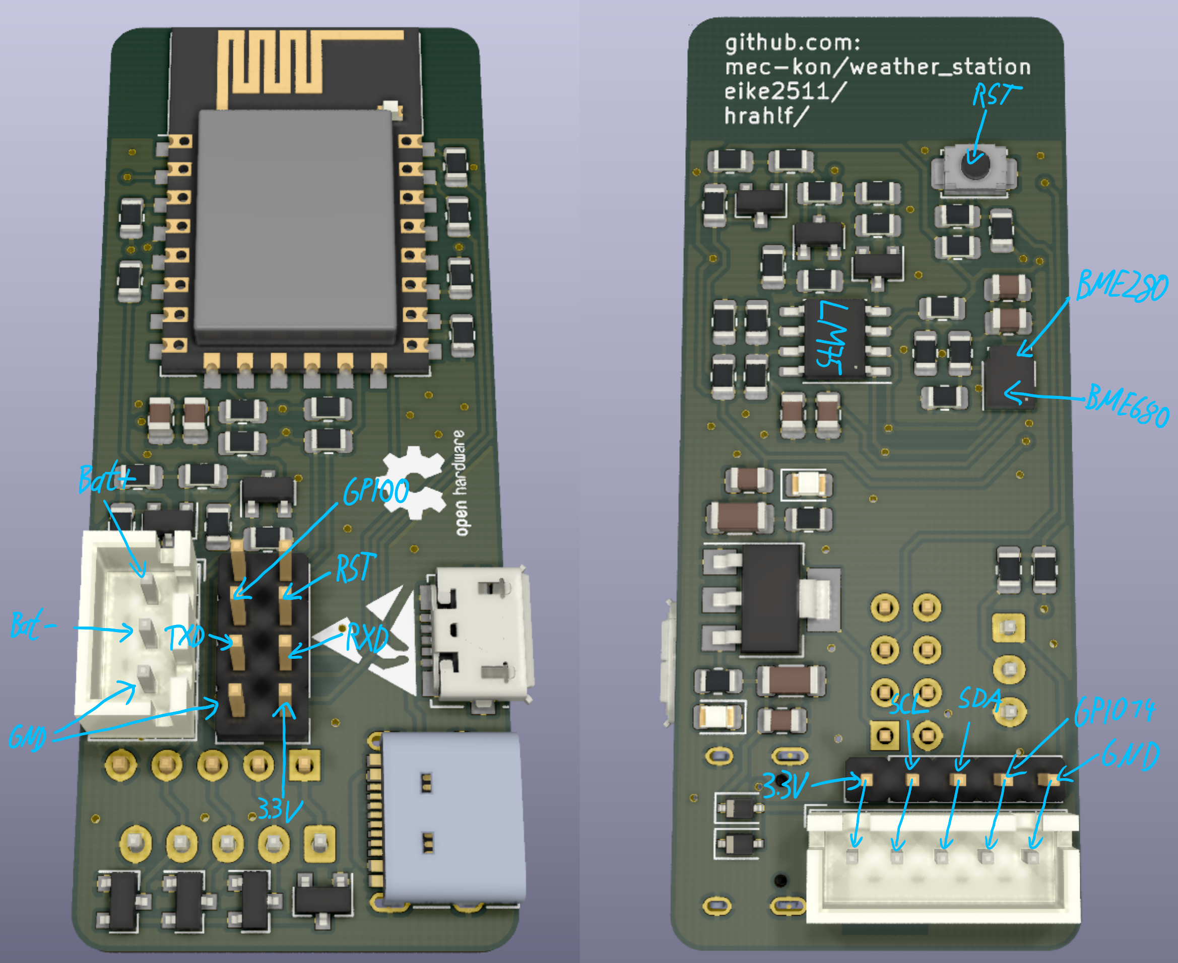
To measure the battery level, it is recommended to use a TP4056 battery charger. An additional device for charging the battery can be connected to it. The upper pin of the JST-XH connector then corresponds to B+, the middle to B- and the lower to GND (B- and OUT- on TP4056).
24.13mmx57.8mm
| Qty | Value | Footprint | References |
|---|---|---|---|
| 13 | 100R | Resistor_SMD:R_0805_2012Metric | R5, R6, R12, R13, R14, R15, R16, R17, R29, R32, R34, R36, R38 |
| 12 | 10kR | Resistor_SMD:R_0805_2012Metric | R1, R3, R4, R7, R9, R11, R19, R22, R23, R26, R27, R35 |
| 4 | NC_100R | Resistor_SMD:R_0805_2012Metric | R30, R31, R33, R37 |
| 3 | 100nF | Capacitor_SMD:C_0805_2012Metric | C5, C8, C10 |
| 3 | 10nF | Capacitor_SMD:C_0805_2012Metric | C3, C7, C9 |
| 3 | BAV99 | Package_TO_SOT_SMD:SOT-23 | D1, D2, D5 |
| 2 | 0R | Resistor_SMD:R_0805_2012Metric | R18, R24 |
| 2 | 1µF | Capacitor_SMD:C_0805_2012Metric | C2, C4 |
| 2 | 4.7µF | Capacitor_SMD:C_1206_3216Metric | C1, C6 |
| 2 | BSS138 | Package_TO_SOT_SMD:SOT-23 | Q1, Q5 |
| 2 | BSS84 | Package_TO_SOT_SMD:SOT-23 | Q2, Q3 |
| 2 | NC_0R | Resistor_SMD:R_0805_2012Metric | R10, R25 |
| 2 | NC_470R | Resistor_SMD:R_0805_2012Metric | R20, R21 |
| 1 | 33kR | Resistor_SMD:R_0805_2012Metric | R8 |
| 1 | 470R | Resistor_SMD:R_0805_2012Metric | R2 |
| 1 | AMS1117-3.3 | Package_TO_SOT_SMD:SOT-223-3_TabPin2 | U2 |
| 1 | BAT48JFILM | Diode_SMD:D_SOD-323 | D4 |
| 1 | BME280 | Package_LGA:Bosch_LGA-8_2.5x2.5mm_P0.65mm_ClockwisePinNumbering | U4 |
| 1 | BZX84Cxx | Diode_SMD:D_SOT-23_ANK | D6 |
| 1 | Conn_01x03 | Connector_JST:JST_XH_B3B-XH-A_1x03_P2.50mm_Vertical | J1 |
| 1 | Conn_01x05 | Connector_JST:JST_XH_B5B-XH-A_1x05_P2.50mm_Vertical | J3 |
| 1 | Conn_01x05_Male | Connector_PinHeader_2.54mm:PinHeader_1x05_P2.54mm_Vertical | J2 |
| 1 | Conn_02x04_Odd_Even | Connector_PinHeader_2.54mm:PinHeader_2x04_P2.54mm_Vertical | J4 |
| 1 | ESP-12F | RF_Module:ESP-12E | U1 |
| 1 | LM75B | Package_SO:SSOP-8_3.9x5.05mm_P1.27mm | U3 |
| 1 | NC_10kR | Resistor_SMD:R_0805_2012Metric | R28 |
| 1 | NC_BAT48JFILM | Diode_SMD:D_SOD-323 | D3 |
| 1 | NC_BME680 | Package_LGA:Bosch_LGA-8_3x3mm_P0.8mm_ClockwisePinNumbering | U5 |
| 1 | NC_BSS138 | Package_TO_SOT_SMD:SOT-23 | Q4 |
| 1 | NC_LED_GREEN | LED_SMD:LED_0805_2012Metric | D7 |
| 1 | NC_LED_RED | LED_SMD:LED_0805_2012Metric | D8 |
| 1 | SW_Push | Button_Switch_SMD_User:SW_Push_SPST_4x3x2 | SW1 |
| 1 | USB_B_Micro | Connector_USB:USB_Micro-B_Molex_47346-0001 | J5 |
| 1 | USB_C_Plug | Connector_USB_User:USB_C_Receptacle_XKB_U262-16XN-4BVC11 | P1 |
ondras12345/electronic-load
Digital control for XHDZ-FZ-2g electronic load

kitspace/component_tester
A keychain version of the Mikrontroller.net AVR component tester

cyntem/piezo_driver_stm32
3-axis PCB and schematics High Voltage Piezo actuator driver with 2 Step motor driver and optional blue-ray microscope (just for test)


It measures 24 × 57.8 mm and has 2 copper layers, 1.6 mm thick.
73 parts, built around the ESP-12F, BME280, AMS1117-3.3 and BAV99. The full list of its parts is on this page, with links to each part's symbol and footprint where PCBKit's library has them.
From the mec-kon/weather_station repository on GitHub, at the commit this page was made from: the board is weather_station.kicad_pcb. PCBKit opens the board in the browser, with nothing to install.
Its repository publishes it under the GPL-3.0 licence: you may reuse it on that licence's terms (keep the author's notice, and for a copyleft licence share your changes alike).