2 layers176 × 50 mm

 meadiode/vin_display1
Vintage display module
Vin display hdsp2000 x20 is an open-source printed circuit board by meadiode, from the meadiode/vin_display repository on GitHub, published under the GPL-3.0 licence. It is a 4-layer board of 148 × 52 mm with 109 parts on 110 nets, routed with 1,664 tracks and 264 vias.
It is built around the RP2040, MIC23050-SYML-TR and W25Q16JVSNIQ, with the SQ4435EY-VB, BSS138 and DMG2301L among its other parts. Its parts include 42 capacitors, 23 ICs, 20 resistors, 7 transistors and 6 connectors. It belongs with the lEDs and displays and retro computing and games boards and the RP2040 boards of this library.


A series of RP2040 based display modules for 3d-printers using dot-matrix, or 16-segment vintage display ICs. Intended to be used with Klipper firmware.
Currently the following displays were built and tested:
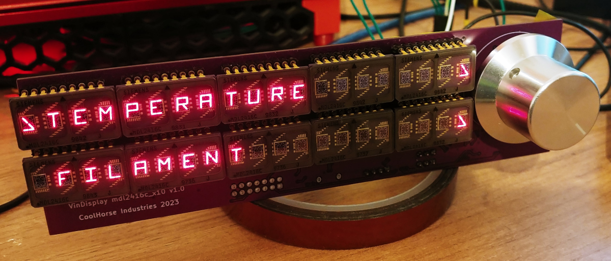
Display module features ten MDL2416C which are 4-character 16-segment LED displays.
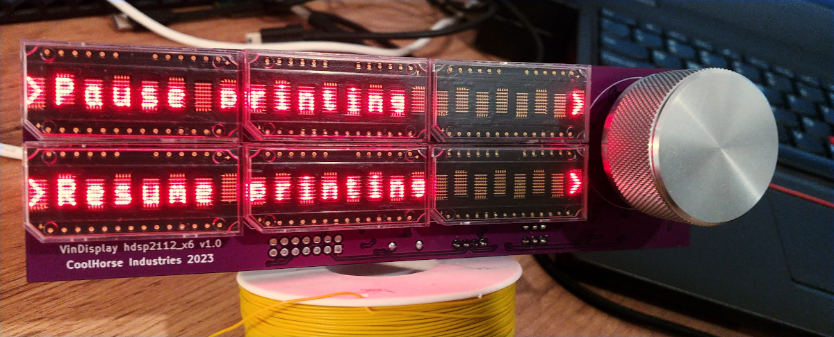
Display module features six HDSP-2112 which are 8-character 5x7 LED dot-matrix displays.
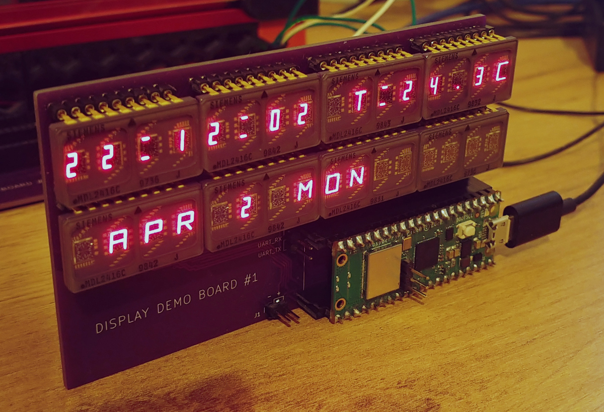
Simplistic demo-board to evaluate MDL2416C(16-segment LED display), 8 of them are driven by a pico_w. The board just displays current time and date and also prints custom message through a web-interface.
Generally, refer to the official Getting started guide
You'll need to have:
The following environment constants should be defined:
PICO_SDK_PATH=/* Path to the root of pico-sdk directory */
FREERTOS_KERNEL_PATH=/* Path to the root of FreeRTOS kernel directory */cd src
mkdir build
cd build
cmake -DCMAKE_BUILD_TYPE=Debug ..
makeConnect the picoprobe to the target pico_w board according to the "getting started guide", then run the following:
cd [Pico OpenOCD source directory]
sudo src/openocd -f interface/picoprobe.cfg -f target/rp2040.cfg -s tcl
It should start a GDB server on the default port 3333.
To flash and run/debug the firmware navigate to the project's directory and run the following:
cd build
gdb-multiarch ./<binary name>.elf
Once GDB started:
target remote :3333
load
monitor init reset
cont| Qty | Value | Footprint | References |
|---|---|---|---|
| 20 | 0.1u | Capacitor_SMD:C_0603_1608Metric | C23, C24, C25, C26, C27, C28, C29, C30, C31, C32, C33, C34, C35, C36, C37, C38 +4 |
| 20 | HDSP-2000 | components:HDSP_DIP12 | U5, U10, U11, U12, U13, U14, U15, U16, U17, U18, U19, U20, U21, U22, U23, U24 +4 |
| 10 | 100n | Capacitor_SMD:C_0603_1608Metric | C5, C6, C7, C8, C9, C10, C11, C12, C13, C14 |
| 7 | 100K | Resistor_SMD:R_0603_1608Metric | R5, R13, R16, R17, R18, R19, R20 |
| 5 | 10K | Resistor_SMD:R_0603_1608Metric | R6, R8, R9, R11, R12 |
| 5 | SQ4435EY | components:SO8_MOSFET_S3G1D4 | Q2, Q3, Q4, Q5, Q6 |
| 4 | 2u2 | Capacitor_SMD:C_0603_1608Metric | C1, C2, C3, C4 |
| 3 | 10n | Capacitor_SMD:C_0603_1608Metric | C18, C19, C20 |
| 3 | 1K | Resistor_SMD:R_0603_1608Metric | R1, R4, R10 |
| 2 | 100R | Resistor_SMD:R_0603_1608Metric | R14, R15 |
| 2 | 19p | Capacitor_SMD:C_0603_1608Metric | C21, C22 |
| 2 | 27R | Resistor_SMD:R_0603_1608Metric | R2, R3 |
| 2 | 4.7uF | Capacitor_SMD:C_0603_1608Metric | C15, C16 |
| 1 | 10A | components:Fuse_2410 | F1 |
| 1 | 12MHz | Crystal:Crystal_SMD_Abracon_ABM8AIG-4Pin_3.2x2.5mm | X1 |
| 1 | 2.2uH | components:Inductor_0806 | L1 |
| 1 | 200R | Resistor_SMD:R_0603_1608Metric | R7 |
| 1 | 560pF | Capacitor_SMD:C_0603_1608Metric | C17 |
| 1 | AUX_CONNECTOR | Connector_IDC:IDC-Header_2x07_P2.54mm_Vertical | J5 |
| 1 | BOOTSEL | components:TS18_TACTILE_SWITCH | SW2 |
| 1 | BSS138 | Package_TO_SOT_SMD:SOT-23 | Q1 |
| 1 | Conn_01x02 | components:Conn_2x3_96 | J6 |
| 1 | D | Diode_SMD:D_SOD-123 | D2 |
| 1 | D | components:Diode_TO252 | D3 |
| 1 | DEBUG | Connector_JST:JST_EH_B3B-EH-A_1x03_P2.50mm_Vertical | J1 |
| 1 | DEBUG_UART | Connector_JST:JST_EH_B3B-EH-A_1x03_P2.50mm_Vertical | J3 |
| 1 | DMG2301L | Package_TO_SOT_SMD:SOT-23 | Q7 |
| 1 | IF_UART | Connector_JST:JST_EH_B4B-EH-A_1x04_P2.50mm_Vertical | J4 |
| 1 | KNOB | components:PEC11H_Encoder | SW3 |
| 1 | MBR1020VL | Diode_SMD:D_SOD-123F | D1 |
| 1 | MIC23050-SYML | Package_DFN_QFN:Micrel_MLF-8-1EP_2x2mm_P0.5mm_EP0.6x1.2mm | U2 |
| 1 | RP2040 | Package_DFN_QFN:QFN-56-1EP_7x7mm_P0.4mm_EP3.2x3.2mm | U3 |
| 1 | SPEAKER | components:BUZZER_CMT-8504 | LS1 |
| 1 | SW_RESET | components:TS18_TACTILE_SWITCH | SW1 |
| 1 | SolderJumper_3_Open | components:Solder_jumber_3pad | JP1 |
| 1 | USB_B_Micro | components:GCT_USB3140 | J2 |
| 1 | W25Q16JVSNIQ | components:SOIC8_150mil | U1 |


meadiode/EMES
Epic Minimalist Entertainment System - DIY handheld handheld game console


Maverick-Shark/X65_BigMiST
The X65 is an ultimate computer for everyone interested in the venerable 65-series of 8-bit and 16-bit CPUs, i.e. the 6502 and 65816.

jackw01/scanlight
A better light source for scanning color negative film

Rack-Robotics/Powercore-V2.0
Open-Source wire EDM power supply by Rack Robotics, Inc.


homelith/pico-disp-ident
Custom firmware to make some RP2040 board working as DVI display tester & identifier
It measures 148 × 52 mm and has 4 copper layers, 1.6 mm thick.
109 parts, built around the RP2040, MIC23050-SYML-TR, W25Q16JVSNIQ and SQ4435EY-VB. The full list of its parts is on this page, with links to each part's symbol and footprint where PCBKit's library has them.
From the meadiode/vin_display repository on GitHub, at the commit this page was made from: the board is hardware/vin_display_hdsp2000_x20/vin_display_hdsp2000_x20.kicad_pcb and its schematic hardware/demo_board1/demo_board1.kicad_sch. PCBKit opens the board in the browser, with nothing to install.
Its repository publishes it under the GPL-3.0 licence: you may reuse it on that licence's terms (keep the author's notice, and for a copyleft licence share your changes alike).