2 layers88.9 × 46.2 mm
Led controller
cruzsbrian/aurora
An addressable LED controller with graphical interface, audio input, and patterns programmed on an SD card.
84 parts3
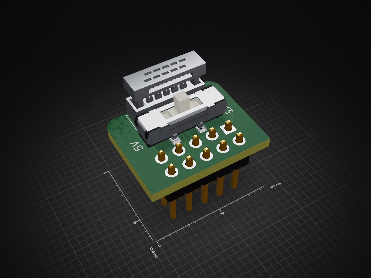
 mdrobot7/debugger-adapters
Aliexpress STLINKv2 debugger to standard connector adapters
Debugger adapter is an open-source printed circuit board by mdrobot7, from the mdrobot7/debugger-adapters repository on GitHub, published under the GPL-3.0 licence. It is a 2-layer board of 17.7 × 13.8 mm with 3 parts on 12 nets, routed with 43 tracks and 3 vias.
It is built around the CL-SB-13A-01T and SFH11-PBPC-D05-ST-BK. Its parts include 2 connectors and 1 switch. It belongs with the interfaces and adapters boards of this library.
Aliexpress STLINKv2 debugger to standard connector adapters
All part links are built into the KiCad parts, just generate the BOM from within KiCad and order. Miscellaneous parts are below.
The ribbon cable IDC connectors for the Cortex-Debug adapter are quite difficult to get exactly right. If the wire goes in at slightly the wrong angle, the conductors will bridge or connect to the wrong pins. After each connector is put on, check each pin with a multimeter to make sure it's not bridged to anything it shouldn't be.
Black Magic Probe and Black Magic Debug are open-source SWD/JTAG debug projects for ARM Cortex microcontrollers. It gives you a bare GDB server and is platform-independent, so it will work on ARM Cortex microcontrollers regardless of brand or series.
To create a Black Magic Probe you need an existing debugger -- another Black Magic Probe, STLink (for ST-based debuggers), Atmel ICE (for Atmel chips), etc.
Keep the SWD wires (between the BMP and the microcontroller) relatively short. SWD doesn't have a length spec, but under 30cm is a good rule of thumb. Slower baud rates will allow for longer lengths. It's recommended to extend the USB side instead of the SWD side.
The Black Magic Probe project switched to Meson in current releases, which makes installation a little harder on Windows. On Windows, your best move is load up a Linux VM using VirtualBox or something similar. You can try to get MSYS2 to work, but no guarantees. Builds and uploads on Windows may need Zadig to manually assign Windows drivers to your BMP, you want to assign it to WinUSB.
Instructions for Linux/Mac:
sudo apt install meson ninja gcc-arm-none-eabi gdb-multiarch binutils-arm-none-eabi dfu-util libhidapi-dev libftdi1-dev libusb-1.0-0-devbrew install meson ninja arm-none-eabi-gcc arm-none-eabi-binutils arm-none-eabi-gdb dfu-util hidapi libftdi libusbgit clone https://codeberg.org/blackmagic-debug/blackmagiccd into the directory you cloned intomeson setup build --reconfigure --cross-file cross-file/stlink.ini -Dtargets=cortexar,cortexm,sam,stm,nxp,ti -Dbmd_bootloader=true
meson compile -C build; meson compile -C boot-binarm-none-eabi-gdb -ex "tar ext [debugger device ID]" -ex "mon s" -ex "att 1" -ex "mon option erase" -ex "load" -batch build/blackmagic_stlink_bootloader.elf
sudo apt install openocd stlink-toolssudo vim /usr/share/openocd/scripts/target/stm32f1x.cfg and add set CPUTAPID 0 below line 35. This disables CPU ID checking (we're flashing a counterfeit).openocd -f interface/stlink-v2.cfg -f target/stm32f1x.cfg -c "init" -c "halt" -c "stm32f1x unlock 0" -c "shutdown" && st-flash erase && st-flash --flash=0x20000 --reset write build/blackmagic_stlink_bootloader.bin 0x8000000sudo dfu-util -l. It should say "found DFU" with some device information.sudo dfu-util -s 0x08002000:leave:force -D build/blackmagic_stlink_firmware.binAll you need to do is git pull the updated BMP firmware (or make any changes you need to), and rebuild. Plug it in via USB and rerun step 11 above. The bootloader handles reflashing the firmware over USB.
Black Magic Probe releases official binaries as well, so you can also download the blackmagic-native BIN file from the Releases page and flash it over DFU. It covers a very similar set of debug targets and fits in the 128KB flash of our counterfeit STLinks.
It measures 17.7 × 13.8 mm and has 2 copper layers, 1.6 mm thick.
3 parts, built around the CL-SB-13A-01T and SFH11-PBPC-D05-ST-BK. The full list of its parts is on this page, with links to each part's symbol and footprint where PCBKit's library has them.
From the mdrobot7/debugger-adapters repository on GitHub, at the commit this page was made from: the board is cortex-debug/debugger-adapter.kicad_pcb and its schematic cortex-debug/debugger-adapter.kicad_sch. PCBKit opens the board in the browser, with nothing to install.
Its repository publishes it under the GPL-3.0 licence: you may reuse it on that licence's terms (keep the author's notice, and for a copyleft licence share your changes alike).
cruzsbrian/aurora
An addressable LED controller with graphical interface, audio input, and patterns programmed on an SD card.


MSTRocketDesignTeam/Avionics-Telemetry-PCB
Rocket Telemetry PCB

wormyrocks/ESPProg-to-altera
Adapter to turn an ESP-Prog into an inexpensive FPGA programmer for use with openFPGALoader.

lhr-solar/VCAT-VehicleControlUnit
Vehicle Control Unit (VCU) for the 2026 Longhorn Racing Solar car

lhr-solar/PS-ChargerInterfacePCB
Interfaces the Elcon charger with the BPS/Battery over CAN

lhr-solar/PS-PumpController
Controls speed of liquid cooling pump and fans for the main battery pack. Additionally, interprets data from temperature sensors and flowrate sensors for fan/pump control loop
