2 layers88.9 × 46.2 mm
Led controller rounded
cruzsbrian/aurora
An addressable LED controller with graphical interface, audio input, and patterns programmed on an SD card.
83 parts3

 cruzsbrian/aurora3
An addressable LED controller with graphical interface, audio input, and patterns programmed on an SD card.
Led controller is an open-source printed circuit board by cruzsbrian, from the cruzsbrian/aurora repository on GitHub. It is a 2-layer board of 88.9 × 46.2 mm with 84 parts on 57 nets, routed with 300 tracks and 184 vias.
It is built around the 74HCT245PW, CL-SB-13A-01T and CMA-4544PF-W, with the SJ-3524-SMT-TR among its other parts. Its parts include 22 resistors, 13 capacitors, 10 connectors, 4 ICs and 2 switches. It belongs with the NXP (LPC, Kinetis, i.MX RT) boards of this library.


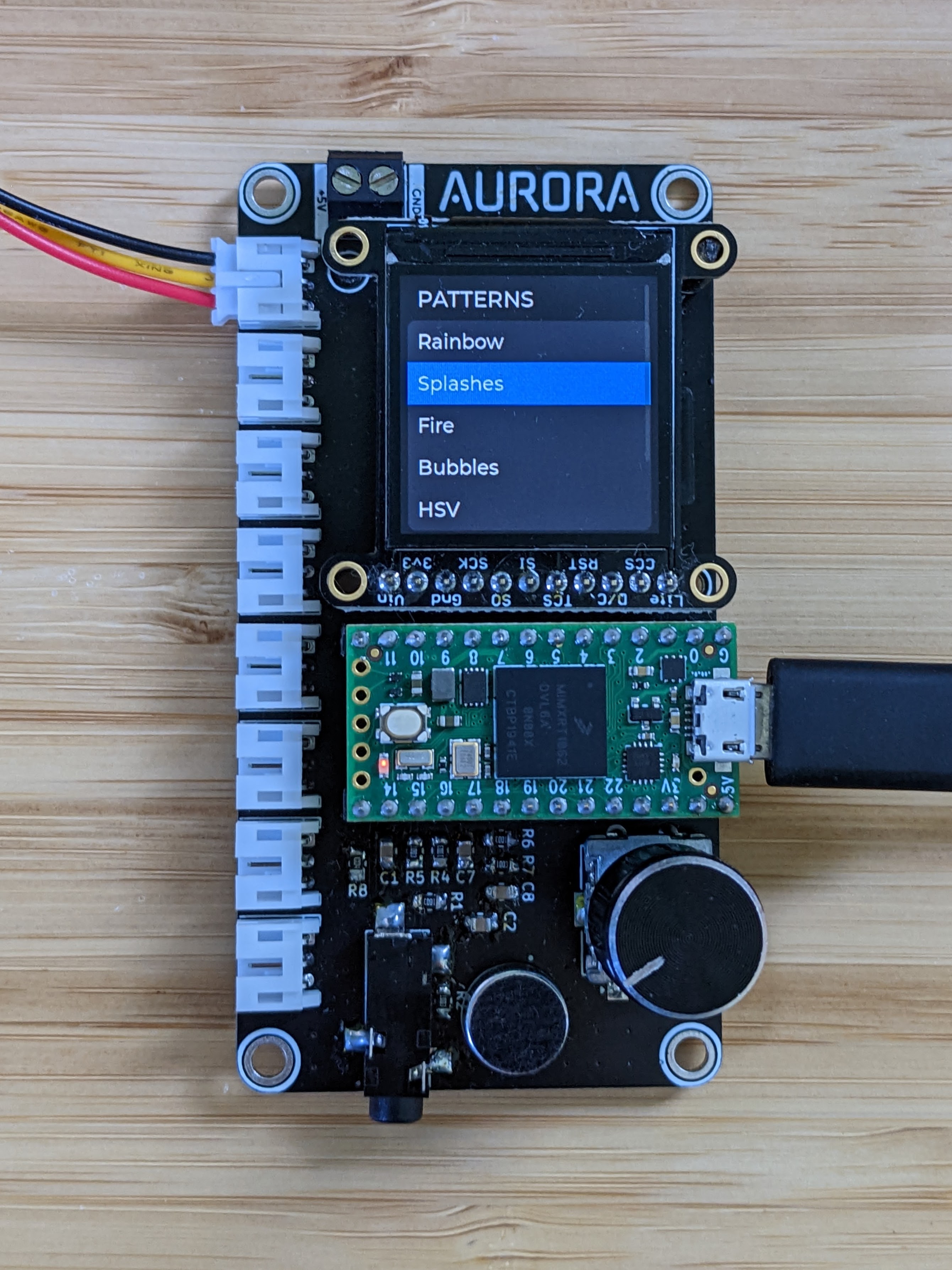
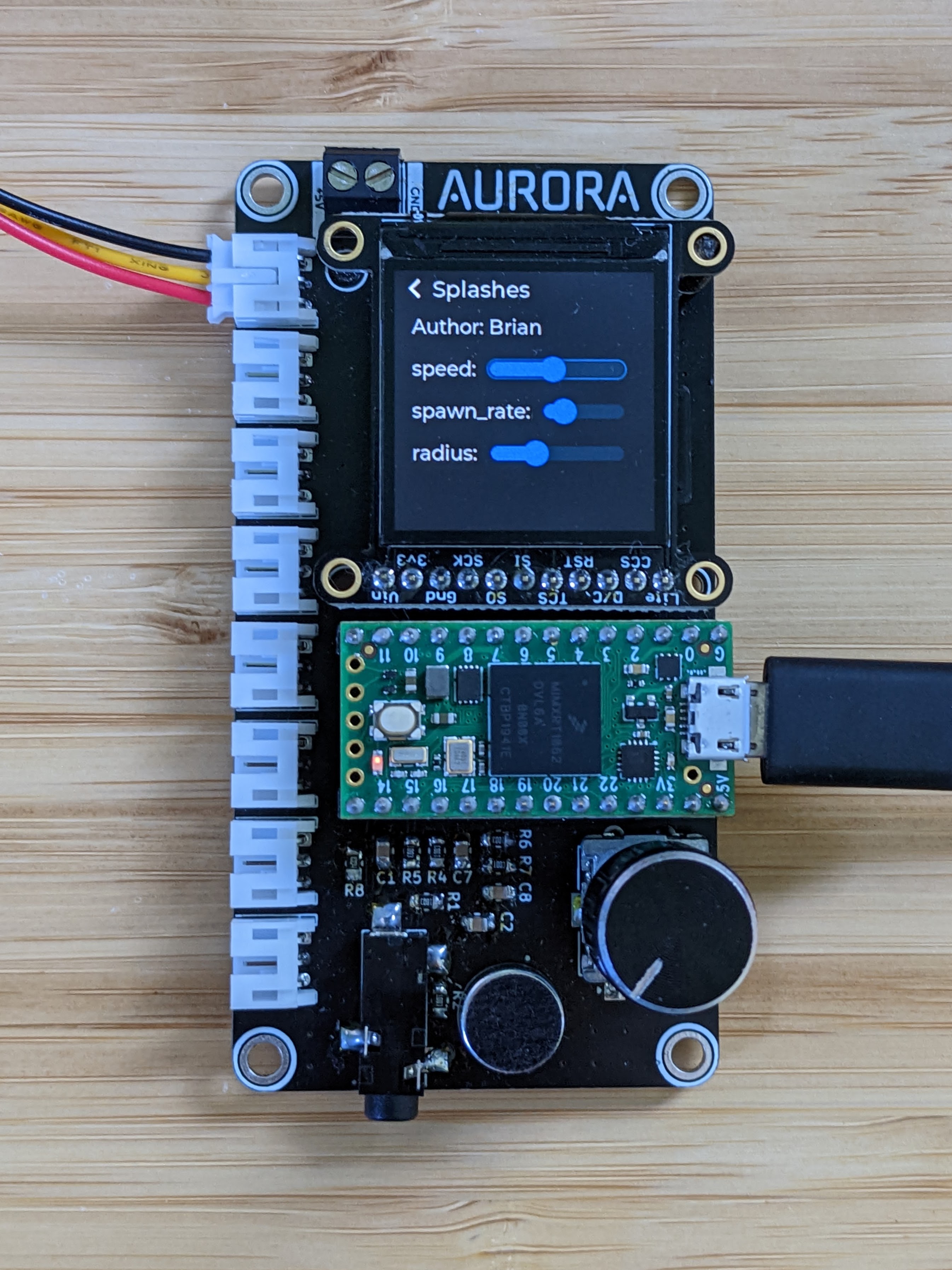
Aurora is an addressable LED controller with a graphical interface, audio input, and patterns programmed on an SD card. It controls up to 8 WS2811-style LED strips in parallel. A microphone and audio jack can be used for music visualization. LED patterns are programmed in Lua and can be modified without rebooting by replacing the SD card.
 |  |
|---|
aurora_sw/src/lights.h contains configuration for the number of strips and their lengths and directions.
N_STRIPS is the total number of strips (starting from the top connector).
LEDS_PER_STRIP the maximum number of LEDs on a single strip.
N_LEDS is the total number of LEDs (the sum of all the strip lengths, less than or equal to N_STRIPS * LEDS_PER_STRIP).
n_leds[N_STRIPS] is an array of the strip lengths.
led_dirs[N_STRIPS] is an array of the strip directions.
1 indicates the strip should start from its first LED, -1 indicates it should start from its last LED.
When an SD card is inserted, Aurora interprets each Lua file in its root directory as a pattern.
The title of a pattern is its filename, minus the .lua extension.
Every pattern must define an update() function to display one frame of its animation, which will be called at 50 Hz.
Patterns can set LED colors with the setRGB(i, r, g, b) and setHSV(i, h, s, v) functions, where i is the index of the LED (starting at 1 to follow the Lua convention) and the other parameters specify the color (all values ranging from 0 to 1).
Patterns can also inspect the current color of an LED with getRGB(i), which returns the red, green, and blue values from 0 to 1.
Calling print(arg1, arg2, ...) from Lua prints to the serial console.
A pattern can specify any number of "parameters" for itself, which appear as sliders in the UI, with add_param(name, min, max, step, default), where name is a string, and max, min, step, default are floating point numbers.
The parameter will then be available as a global variable in the Lua environment for that pattern (so name must be a valid Lua variable name).
Here is an example pattern which displays a rainbow repeated a configurable number of times (set by cycles) moving at a configurable speed:
add_param("speed", 0, 1, 0.05, 0.15)
add_param("cycles", 1, 10, 1, 1)

start = 0

function update()
    for i=1,N_LEDS do
        -- Calculate hue based on LED position, rainbow start position, and number of cycles.
        h = ((i - start) * cycles / N_LEDS) % 1

        -- Set LED to calculated hue, full saturation, 25% brightness.
        setHSV(i, h, 1, 0.25)
    end

    start = start + speed
endAlthough you can run the Aurora firmware as-is, you will probably want to go in and customize the LED settings to match the specific layout of your installation. This customization is done in the aurora_sw/src/lights.h file as follows. Examples are included for a few different possible configurations.
Important Parameters:
Write-up Coming Soon!
The Linux install instructions assume that you have Version 1.x.x of the Arduino IDE installed, along with teensyduino which is used to upload code to the Teensy. Instructions for installing teensyduino (and links to arduino installers) can be found here: https://www.pjrc.com/teensy/teensyduino.html. It is definitely worth checking that your install works by uploading one of the teensy example scripts before proceeding.
Setting up the build environment is pretty straightforward, but it does involve mucking around in the arduino libraries folder. If you have any questions definitely feel free to reach out.
Using the arduino IDE Install: (Sketch -> Include Library -> Manage Libraries...)
Navigate to your a libraries folder (likely /home/[name]/Arduino/libraries) and clone the arduinoLua repo.
Now copy the lv_conf.h file from /aurora_sw/src/ to the top level of your Arduino libraries folder. This configures the GUI generator.
In your arduino libraries folder, replace TFT_eSPI/User_Setup.h with the User_Setup.h file provided in aurora_sw/src/. This configures the pins and dimensions of the display itself.
Rename /aurora_sw/src/main.cpp to /aurora_sw/src/main.ino so that it will be detected by the Arduino IDE.
You can now open src.ino with the Arduino IDE.
Before uploading you will need to set the optimizer (tools -> optimize) to "Smallest Code".
You are now ready to upload!
| Qty | Value | Footprint | References |
|---|---|---|---|
| 8 | 100 | Resistor_SMD:R_0805_2012Metric_Pad1.20x1.40mm_HandSolder | R13, R14, R15, R16, R17, R18, R19, R20 |
| 8 | Conn_01x03 | Connector_JST:JST_PH_S3B-PH-K_1x03_P2.00mm_Horizontal | J3, J4, J5, J6, J7, J8, J9, J10 |
| 8 | G*** | kibuzzard-62AD6AEC | kibuzzard-62AD6AEC, kibuzzard-62AD6AEC1, kibuzzard-62AD6AEC2, kibuzzard-62AD6AEC3, kibuzzard-62AD6AEC4, kibuzzard-62AD6AEC5, kibuzzard-62AD6AEC6, kibuzzard-62AD6AEC7 |
| 8 | G*** | kibuzzard-62AD6B04 | kibuzzard-62AD6B1, kibuzzard-62AD6B2, kibuzzard-62AD6B3, kibuzzard-62AD6B04, kibuzzard-62AD6B4, kibuzzard-62AD6B5, kibuzzard-62AD6B6, kibuzzard-62AD6B7 |
| 7 | 100k | Resistor_SMD:R_0805_2012Metric_Pad1.20x1.40mm_HandSolder | R1, R2, R4, R5, R6, R7, R22 |
| 4 | 10k | Resistor_SMD:R_0805_2012Metric_Pad1.20x1.40mm_HandSolder | R9, R10, R11, R12 |
| 4 | 10u | Capacitor_SMD:C_0805_2012Metric_Pad1.18x1.45mm_HandSolder | C1, C2, C3, C13 |
| 4 | MountingHole_Pad | MountingHole:MountingHole_3.2mm_M3_ISO14580_Pad | H1, H2, H3, H4 |
| 2 | 0.47u | Capacitor_SMD:C_0805_2012Metric_Pad1.18x1.45mm_HandSolder | C4, C5 |
| 2 | 10n | Capacitor_SMD:C_0805_2012Metric_Pad1.18x1.45mm_HandSolder | C9, C10 |
| 2 | 47n | Capacitor_SMD:C_0805_2012Metric_Pad1.18x1.45mm_HandSolder | C7, C8 |
| 1 | 0.1u | Capacitor_SMD:C_0805_2012Metric_Pad1.18x1.45mm_HandSolder | C11 |
| 1 | 150k | Resistor_SMD:R_0805_2012Metric_Pad1.20x1.40mm_HandSolder | R21 |
| 1 | 1M | Resistor_SMD:R_0805_2012Metric_Pad1.20x1.40mm_HandSolder | R8 |
| 1 | 1u | Capacitor_SMD:C_0805_2012Metric_Pad1.18x1.45mm_HandSolder | C12 |
| 1 | 2.2k | Resistor_SMD:R_0805_2012Metric_Pad1.20x1.40mm_HandSolder | R3 |
| 1 | 2.2u | Capacitor_SMD:C_0805_2012Metric_Pad1.18x1.45mm_HandSolder | C6 |
| 1 | 74HCT245PW | Package_SO:TSSOP-20_4.4x6.5mm_P0.65mm | U2 |
| 1 | Adafruit_TFT_1in3_ST7789 | displays:Adafruit_TFT_1in3_ST7789 | U4 |
| 1 | CL-SB-13A-01T | SP3T-CL-SB-13A-01T:CL-SB-13A-01T | SW2 |
| 1 | CMA-4544PF-W | CMA-4544PF-W:MIC_CMA-4544PF-W | MK1 |
| 1 | G*** | kibuzzard-62AD6C16 | kibuzzard-62AD6C16 |
| 1 | G*** | kibuzzard-62AD6C27 | kibuzzard-62AD6C27 |
| 1 | G*** | kibuzzard-62AD66A7 | kibuzzard-62AD66A7 |
| 1 | G*** | kibuzzard-62AD6BA8 | kibuzzard-62AD6BA8 |
| 1 | G*** | kibuzzard-62AD6BC2 | kibuzzard-62AD6BC2 |
| 1 | G*** | kibuzzard-62AD5F1D | kibuzzard-62AD5F1D |
| 1 | G*** | kibuzzard-62AD6C4C | kibuzzard-62AD6C4C |
| 1 | G*** | kibuzzard-62AD66B6 | kibuzzard-62AD66B6 |
| 1 | G*** | kibuzzard-62AD5F34 | kibuzzard-62AD5F34 |
| 1 | G*** | kibuzzard-62AD6C38 | kibuzzard-62AD6C38 |
| 1 | G*** | kibuzzard-62AD6B13 | kibuzzard-62AD6B13 |
| 1 | G*** | kibuzzard-62AD6C62 | kibuzzard-62AD6C62 |
| 1 | MAX9814 | Package_DFN_QFN:TDFN-14-1EP_3x3mm_P0.4mm_EP1.78x2.35mm_ThermalVias | U1 |
| 1 | RotaryEncoder_Switch | Rotary_Encoder:RotaryEncoder_Alps_EC11E-Switch_Vertical_H20mm | SW1 |
| 1 | SJ-3524-SMT | SJ-3524-SMT:CUI_SJ-3524-SMT | J2 |
| 1 | Screw_Terminal_01x02 | terminal_block:TerminalBlock_Molex_393570002_1x02_P3.50mm_Horizontal | J1 |
| 1 | Teensy4.0 | teensy_library:Teensy40 | U3 |
It measures 88.9 × 46.2 mm and has 2 copper layers, 1.6 mm thick.
84 parts, built around the 74HCT245PW, CL-SB-13A-01T, CMA-4544PF-W and SJ-3524-SMT-TR. The full list of its parts is on this page, with links to each part's symbol and footprint where PCBKit's library has them.
From the cruzsbrian/aurora repository on GitHub, at the commit this page was made from: the board is aurora_hw/led_controller.kicad_pcb and its schematic aurora_hw/led_controller.kicad_sch. PCBKit opens the board in the browser, with nothing to install.
Its repository states no licence, so its author keeps all rights: ask cruzsbrian before reusing the design.
cruzsbrian/aurora
An addressable LED controller with graphical interface, audio input, and patterns programmed on an SD card.

mdrobot7/debugger-adapters
Aliexpress STLINKv2 debugger to standard connector adapters

garrettsworkshop/RAM128
128 kB Saturn 128k-compatible RAM expansion card for Apple II

jdelahayes/KCNC-GRBL_SHIELD_PCB
Ceci est un shield GRBL pour Arduino Uno adapté à la R-CNC (makerfr.com).


DangerousPrototypes/BusPirate5-hardware
Bus Pirate Hardware and accessories for v5 and higher

PCBench/PCBench
resolution = [0.5, 0.5] pcbfolder = '../PCBs/' pcbnames = ["1Bitsy1bitsy"] iters = 30 env = PCBRoutingEnv(resolution=resolution, pcbfolder=pcbfolder, pcbnames=pcbnames) obs, info = env.reset() for in range(iters): act =…
