4 layers100 × 83 mm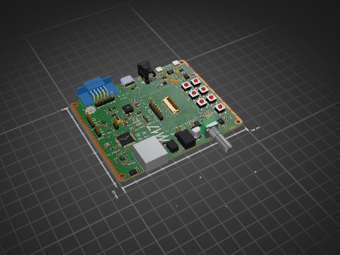
Module17-Mainboard
M17-Project/Module_17
M17 modem board for 9600-baud capable radios
209 parts129CERN-OHL-W-2.0

 mdiepart/NXP_K22_testboard
NXP K22 testboard is an open-source printed circuit board by mdiepart, from the mdiepart/NXP_K22_testboard repository on GitHub. It is a 4-layer board of 60 × 90 mm with 64 parts on 82 nets, routed with 631 tracks and 335 vias.
It is built around the MK22FN512VLH12, W25Q32JVSSIQ and AMS1117-3.3, with the USBLC6-2SC6, MPZ1608Y221BTA00 and T495D226K035ATE125 among its other parts. Its parts include 19 capacitors, 14 resistors, 11 connectors, 4 ICs and 2 crystals. It belongs with the NXP (LPC, Kinetis, i.MX RT) boards of this library.


| Qty | Value | Footprint | References |
|---|---|---|---|
| 11 | 100n | Capacitor_SMD:C_0603_1608Metric | C206, C207, C208, C209, C211, C212, C213, C214, C218, C219, C301 |
| 5 | 100 | Resistor_SMD:R_0603_1608Metric | R304, R305, R306, R307, R308 |
| 5 | NetTie_2 | M17_misc_passive:NetTie-2_SMD_Pad0.2mm | NT201, NT202, NT203, NT204, NT205 |
| 4 | TestPoint | TestPoint:TestPoint_Pad_D1.5mm | TP202, TP203, TP204, TP205 |
| 3 | 10k | Resistor_SMD:R_0603_1608Metric | R203, R204, R205 |
| 3 | 33 | Resistor_SMD:R_0603_1608Metric | R201, R202, R206 |
| 2 | 1n | Capacitor_SMD:C_0603_1608Metric | C210, C217 |
| 2 | 1u | Capacitor_SMD:C_0603_1608Metric | C201, C205 |
| 2 | 20p | Capacitor_SMD:C_0603_1608Metric | C202, C203 |
| 2 | 5k1 | Resistor_SMD:R_0603_1608Metric | R302, R303 |
| 1 | 0 | Resistor_SMD:R_0603_1608Metric | R301 |
| 1 | 10p | Capacitor_SMD:C_0603_1608Metric | C216 |
| 1 | 220R@100M | Inductor_SMD:L_0603_1608Metric | FB201 |
| 1 | 22u | Capacitor_Tantalum_SMD:CP_EIA-7343-31_Kemet-D | C204 |
| 1 | 32.768 kHz | Crystal:Crystal_SMD_3215-2Pin_3.2x1.5mm | Y201 |
| 1 | AMS1117-3.3 | Package_TO_SOT_SMD:SOT-223-3_TabPin2 | U201 |
| 1 | Analog | Connector_PinSocket_2.54mm:PinSocket_1x08_P2.54mm_Vertical | J307 |
| 1 | Barrel_Jack | Connector_BarrelJack:BarrelJack_CLIFF_FC681465S_SMT_Horizontal | J301 |
| 1 | CLK | TestPoint:TestPoint_Pad_D2.0mm | TP206 |
| 1 | Conn_ARM_JTAG_SWD_10 | Connector_PinHeader_1.27mm:PinHeader_2x05_P1.27mm_Vertical_SMD | J302 |
| 1 | D_Schottky | Diode_SMD:D_SOD-323 | D301 |
| 1 | ECS-TXO-3225MV | M17_misc_active:ECS-TXO_3.2x2.5mm | X201 |
| 1 | MK22FN512 | Package_QFP:LQFP-64_10x10mm_P0.5mm | U202 |
| 1 | OLED | Connector_PinSocket_2.54mm:PinSocket_1x07_P2.54mm_Vertical | J308 |
| 1 | PortA | Connector_PinSocket_2.54mm:PinSocket_1x05_P2.54mm_Vertical | J303 |
| 1 | PortB | Connector_PinSocket_2.54mm:PinSocket_1x08_P2.54mm_Vertical | J304 |
| 1 | PortC | Connector_PinSocket_2.54mm:PinSocket_1x08_P2.54mm_Vertical | J305 |
| 1 | PortD | Connector_PinSocket_2.54mm:PinSocket_1x08_P2.54mm_Vertical | J306 |
| 1 | Power | Connector_PinSocket_2.54mm:PinSocket_1x06_P2.54mm_Vertical | J310 |
| 1 | SW_Push | Button_Switch_SMD:SW_SPST_PTS645 | SW201 |
| 1 | UART | Connector_PinSocket_2.54mm:PinSocket_1x03_P2.54mm_Vertical | J309 |
| 1 | USBLC6-2SC6 | Package_TO_SOT_SMD:SOT-23-6 | U301 |
| 1 | USB_C_Receptacle_USB2.0_14P | Connector_USB:USB_C_Receptacle_HRO_TYPE-C-31-M-12 | J311 |
| 1 | W25Q32JVSS | Package_SO:SOIC-8_5.23x5.23mm_P1.27mm | U203 |
The 63 most common of 64 parts.
M17-Project/Module_17
M17 modem board for 9600-baud capable radios

swiszczoo/adat_usb_interface
16-in, 16-out 4x ADAT <=> USB interface supporting USB Audio Class 2.0


alvarop/swd2usbc
Have you ever wanted to debug your device over USB-C? Sometimes there's not enough room for a JTAG/SWD connector, or even Tag-Connect pads!

National-Association-of-Rocketry-UCD/2025_NAR_CanSat
PCB and schematic files can be accesed by downloading KiCADCamsatPCB as a zip file and then opening the KiCAD project file.

Arhamee/hardware-portfolio
Multi-layer PCB designs in KiCad 10 schematic capture to fabrication-ready Gerbers. High-speed routing, BGA escape, power electronics.

alph4345/test
TrinketCore puts everything a small rechargeable gadget needs on one 40 × 60 mm board, ready to order assembled from PCBWay:
It measures 60 × 90 mm and has 4 copper layers, 1.61 mm thick.
64 parts, built around the MK22FN512VLH12, W25Q32JVSSIQ, AMS1117-3.3 and USBLC6-2SC6. The full list of its parts is on this page, with links to each part's symbol and footprint where PCBKit's library has them.
From the mdiepart/NXP_K22_testboard repository on GitHub, at the commit this page was made from: the board is NXP_K22_TestBoard/NXP_K22_TestBoard.kicad_pcb and its schematic NXP_K22_TestBoard/NXP_K22_TestBoard.kicad_sch. PCBKit opens the board in the browser, with nothing to install.
Its repository states no licence, so its author keeps all rights: ask mdiepart before reusing the design.