
2 layers44.3 × 46.3 mm
Catear pcb
TobleMiner/catear-pcb
This repo contains the PCB for the Nekomimi project of @BenBE . It will be used to illuminate 3D printed catears.
121 parts1
 mdh1418/LabMonitorUROP
UROP with Prof. Joe Steinmeyer to bring out a low cost and small footprint system to monitor environmental data within a laboratory setting.
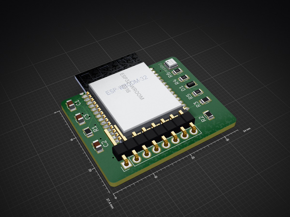
Prototype is an open-source printed circuit board by mdh1418, from the mdh1418/LabMonitorUROP repository on GitHub. It is a 2-layer board of 34 × 27.4 mm with 13 parts on 39 nets, routed with 147 tracks and 22 vias.
It is built around the ESP32-WROOM-32 and BME680. Its parts include 6 resistors, 3 capacitors, 2 ICs and 1 diode. It belongs with the ESP32 boards of this library.


UROP with Prof. Joe Steinmeyer to bring out a low cost and small footprint system to monitor environmental data within a laboratory setting.
For this project, we are using the ESP32 (https://www.espressif.com/en/products/hardware/esp32/overview), the BME680 environmental sensor (https://cdn-shop.adafruit.com/product-files/3660/BME680.pdf), as well as a customized PCB for a minimal barebones setup. The ESP32 and BME680 are interfaced using I2C.
Materials
After installing the software listed below in the Software section to program the ESP32-DevKitC with Arduino, simply follow the hookup guide outlined in the Adafruit tutorial linked above in the materials list.
Materials
After installing the software listed below in the Software section to program the ESP-Wroom-32, (
Notes
Programming the ESP32 with Arduino https://github.com/espressif/arduino-esp32
BME680 Driver https://github.com/BoschSensortec/BME680_driver
KiCad (If customizing PCB) http://kicad-pcb.org/
http://esp32.net/ https://www.espressif.com/sites/default/files/documentation/esp32_hardware_design_guidelines_en.pdf https://www.espressif.com/sites/default/files/documentation/esp-wroom-32_datasheet_en.pdf https://3.bp.blogspot.com/-zyGHuqISKPs/WMx4MWPAZOI/AAAAAAAAAMw/xxDcpwVSq0garkCG5n8yQfn4X7r94zMHACLcB/s1600/ESP%2B32%2BSchematic.PNG https://cdn-shop.adafruit.com/product-files/3660/BME680.pdf https://learn.adafruit.com/adafruit-bme680-humidity-temperature-barometic-pressure-voc-gas/arduino-wiring-test https://www.14core.com/wiring-and-flashing-programming-esp-32-esp32s-with-usb-ttl-uart/ https://github.com/sparkfun/SparkFun-KiCad-Libraries https://www.wayneandlayne.com/blog/2013/02/27/kicad-tutorial-gerber-file-generation/ https://techtutorialsx.com/2017/04/24/esp32-publishing-messages-to-mqtt-topic/
| Qty | Value | Footprint | References |
|---|---|---|---|
| 3 | 10K | Resistors_SMD:R_0805 | R4, R5, R6 |
| 2 | 5K(1%)(NC) | Resistors_SMD:R_0805 | R2, R3 |
| 1 | 100uF/6.3V(20%) | Capacitors_SMD:C_0805 | C1 |
| 1 | 12K(1%) | Resistors_SMD:R_0805 | R1 |
| 1 | 1N4148 | Diodes_SMD:D_0805 | D1 |
| 1 | 1nF/50V(10%) | Capacitors_SMD:C_0805 | C2 |
| 1 | 1uF/10V(10%) | Capacitors_SMD:C_0805 | C3 |
| 1 | BME680 | BME680:BME680 | U2 |
| 1 | Conn_01x08 | Socket_Strips:Socket_Strip_Straight_1x08_Pitch2.54mm | G 3V EN 16 TX RX D0 G |
| 1 | ESP32-WROOM | ESP32-footprints-Lib:ESP32-WROOM | U1 |
TobleMiner/catear-pcb
This repo contains the PCB for the Nekomimi project of @BenBE . It will be used to illuminate 3D printed catears.

fjuliofontes/esp32-iaq-sensor
Bosch Sensortec BME680 Indoor-air-quality monitor based


klaus-liebler/labathome
Der kleine Bruder von lab@home. Ermöglicht das Experimentieren mit PT1...PTn-Gliedern, die intern als RC-Kombination (entkoppelt über Operationsverstärker) ausgeführt sind.

pypilot/pypilot_mfd
lcd display for various types of marine data including nmea0183, signalk and pypilot


jfm92/everAliveSensor
Solar-powered BLE environmental sensor (temp, humidity, pressure) with a 50F supercapacitor — potentially infinite lifetime, 19-day dark autonomy. ESP32 + BME680. Experimental.

It measures 34 × 27.4 mm and has 2 copper layers, 1.6 mm thick.
13 parts, built around the ESP32-WROOM-32 and BME680. The full list of its parts is on this page, with links to each part's symbol and footprint where PCBKit's library has them.
From the mdh1418/LabMonitorUROP repository on GitHub, at the commit this page was made from: the board is LabMonitor/LabMonitor/Kicad/Prototype/Prototype.kicad_pcb. PCBKit opens the board in the browser, with nothing to install.
Its repository states no licence, so its author keeps all rights: ask mdh1418 before reusing the design.