2 layers70 × 35 mm
 mcranford13/Ps2Plus34
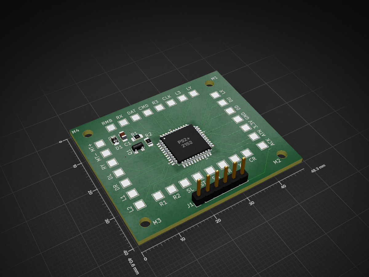
PS2 controller emulator designed for the PIC16F18876
Ps2Plus is an open-source printed circuit board by mcranford13, from the mcranford13/Ps2Plus repository on GitHub, published under the GPL-3.0 licence. It is a 2-layer board of 48.3 × 40.6 mm with 41 parts on 46 nets, routed with 171 tracks and 4 vias.
Its parts include 5 resistors, 3 inductors, 1 capacitor, 1 IC and 1 diode.
This project is a work in progress for making a PS2 Controller emulator. It was designed for the PIC16F18876 microcontroller. As of right now the controller emulation is working great. There are still some features that I want to add but the main part of the project is complete.
There are several hold-ups keeping this project from being complete, the main one being that writing an application for the PS2 and being able to send custom commands to the controller is difficult. I am slowly deciphering everything done by the PS2Dev team but it is slow going. If anyone would like to contribute or offer help/advice, I would gladly take it.
This project consists of several smaller projects each with its own folder, and is, as follows:
firmware - Main code of the project. Contains the PS2 protocol code.
hardware - The schematics and pcb design of the project. Includes information regarding external circuitry.
updater - The PS2 application for updating the controller.
bootloader - The bootloader code for the mcu.
docs - Contains datasheets, pinouts, and other useful documentation.
You will need a pickit3, MPLAB (free), and XC8 compiler to flash this. To build from source, open the firmware project in MPLAB and click 'run'. This will compile the project and then initiate the transfer to the mcu.
The correct pinout of the microcontroller can be found in the docs folder.
- Press Select, L1, and L2 to enter configuration mode. The PS2 should say that there is no controller connected (if you are in a game).
- Move the analog sticks slowly in a circle.
- Press Select, L1, and R1 to exit. The PS2 should now recognize the controller.
- Reboot the controller (rebooting the ps2 works too). Analog sticks should now be working.
To set the analog sticks back to the default values:
- Press Select, L1, and L2 to enter configuration mode.
- Press L2, R2, Select, Start.
- Reboot controller (or ps2).
Please note that this is my first pcb design and if there are mistakes or any room for improvement please make an issue or a pull request. I am always happy to learn and improve.
I have recieved feedback that the pad layout of the pcb is not optimal, this occured due to the pins chosen during the prototyping phase and when I switched from the DIP to the TQFP. I intend to update this but I am been really busy with school and life. Therefore I will release it how it is for now, and update it when I get a chance. If anyone would like to submit an updated pcb, I'd be happy to include it. Thanks for your understanding.
This project has only moved forward due to these individuals and sites (in no particular order):
| Qty | Value | Footprint | References |
|---|---|---|---|
| 4 | MountingHole_2.7mm | MountingHole:MountingHole_2.7mm | M1, M2, M3, M4 |
| 1 | 100K | Resistor_SMD:R_0805_2012Metric_Pad1.15x1.40mm_HandSolder | R1 |
| 1 | 10uF | Capacitor_SMD:C_0805_2012Metric_Pad1.15x1.40mm_HandSolder | C1 |
| 1 | 1K | Resistor_SMD:R_0805_2012Metric_Pad1.15x1.40mm_HandSolder | R2 |
| 1 | 1N58XX | Diode_SMD:D_0805_2012Metric_Pad1.15x1.40mm_HandSolder | D1 |
| 1 | 2N7000 | Package_TO_SOT_SMD:SOT-23 | Q1 |
| 1 | 3.3V | TestPoint:TestPoint_Pad_2.0x2.0mm | 3.3V |
| 1 | ACK | TestPoint:TestPoint_Pad_2.0x2.0mm | ACK |
| 1 | ATN | TestPoint:TestPoint_Pad_2.0x2.0mm | ATN |
| 1 | CIR | TestPoint:TestPoint_Pad_2.0x2.0mm | CR |
| 1 | Conn_01x06_Female | Connector_PinHeader_2.54mm:PinHeader_1x06_P2.54mm_Vertical | J1 |
| 1 | DD | TestPoint:TestPoint_Pad_2.0x2.0mm | DD |
| 1 | GND | TestPoint:TestPoint_Pad_2.0x2.0mm | GND |
| 1 | MTR+ | TestPoint:TestPoint_Pad_2.0x2.0mm | MT+ |
| 1 | MTR- | TestPoint:TestPoint_Pad_2.0x2.0mm | MT- |
| 1 | PS2+ | PIC16F18876-I_PT:QFP80P1200X1200X120-44N | U1 |
| 1 | R1 | TestPoint:TestPoint_Pad_2.0x2.0mm | R1 |
| 1 | R2 | TestPoint:TestPoint_Pad_2.0x2.0mm | R2 |
| 1 | RMB | TestPoint:TestPoint_Pad_2.0x2.0mm | RMB |
| 1 | SL | TestPoint:TestPoint_Pad_2.0x2.0mm | SL |
| 1 | SQ | TestPoint:TestPoint_Pad_2.0x2.0mm | SQ |
| 1 | ST | TestPoint:TestPoint_Pad_2.0x2.0mm | ST |
| 1 | TP10 | TestPoint:TestPoint_Pad_2.0x2.0mm | L2 |
| 1 | TP11 | TestPoint:TestPoint_Pad_2.0x2.0mm | RX |
| 1 | TP12 | TestPoint:TestPoint_Pad_2.0x2.0mm | DAT |
| 1 | TP13 | TestPoint:TestPoint_Pad_2.0x2.0mm | CMD |
| 1 | TP18 | TestPoint:TestPoint_Pad_2.0x2.0mm | R3 |
| 1 | TP19 | TestPoint:TestPoint_Pad_2.0x2.0mm | CLK |
| 1 | TP20 | TestPoint:TestPoint_Pad_2.0x2.0mm | L3 |
| 1 | TP23 | TestPoint:TestPoint_Pad_2.0x2.0mm | LY |
| 1 | TP26 | TestPoint:TestPoint_Pad_2.0x2.0mm | LX |
| 1 | TP27 | TestPoint:TestPoint_Pad_2.0x2.0mm | DU |
| 1 | TP4 | TestPoint:TestPoint_Pad_2.0x2.0mm | RY |
| 1 | TP7 | TestPoint:TestPoint_Pad_2.0x2.0mm | DL |
| 1 | TP8 | TestPoint:TestPoint_Pad_2.0x2.0mm | DR |
| 1 | TP9 | TestPoint:TestPoint_Pad_2.0x2.0mm | L1 |
| 1 | TRI | TestPoint:TestPoint_Pad_2.0x2.0mm | TR |
| 1 | X | TestPoint:TestPoint_Pad_2.0x2.0mm | X |
It measures 48.3 × 40.6 mm and has 2 copper layers, 1.6 mm thick.
41 parts. The full list of its parts is on this page, with links to each part's symbol and footprint where PCBKit's library has them.
From the mcranford13/Ps2Plus repository on GitHub, at the commit this page was made from: the board is hardware/ps2plus.kicad_pcb. PCBKit opens the board in the browser, with nothing to install.
Its repository publishes it under the GPL-3.0 licence: you may reuse it on that licence's terms (keep the author's notice, and for a copyleft licence share your changes alike).

VoronDesign/Voron-Hardware
Cool Hardware designed by the Voron Design group

hackclub/OnBoard
💡 Join 1,000 teenagers and make your first PCB with a $100 grant!

openwch/ch32v003
CH32V003 is an ultra-cheap RISC-V MCU with 2KB SRAM, 16KB flash, and up to 18 GPIOs that sells for under $0.10

imchipwood/dumbpad
Simple 4x4 numpad with rotary encoder. Powered by QMK via ATmega32u4 Pro Micro

jrsteensen/OpenHornet
OpenHornet 1:1 F/A-18C Simulator Repository


fabiansteiner/OpenValve
3D-printable pinch valve for irrigation and sensor-driven liquid control.