

4 layers35 × 35 mm
Lemon pepper
VIPQualityPost/lemon-pepper-stepper
simplefoc all-in-one 50W hybrid stepper + bldc driver
87 parts75MIT

 mcells/mt6835-hoverboard-motor29
MT6835 magnetic Encoder Breakout board, eg. for mounting inside Hoverboard motors
Mt6835-hoverboard is an open-source printed circuit board by mcells, from the mcells/mt6835-hoverboard-motor repository on GitHub. It is a 2-layer board of 24 × 32 mm with 14 parts on 14 nets, routed with 186 tracks and 7 vias.
It is built around the MT6835 and BDFN2A051U. Its parts include 3 connectors, 2 capacitors, 1 IC and 1 diode. It belongs with the robots and motor control boards of this library.
MT6835 Breakout board, eg. for mounting inside Hoverboard motors
| Front | Back |
|---|---|
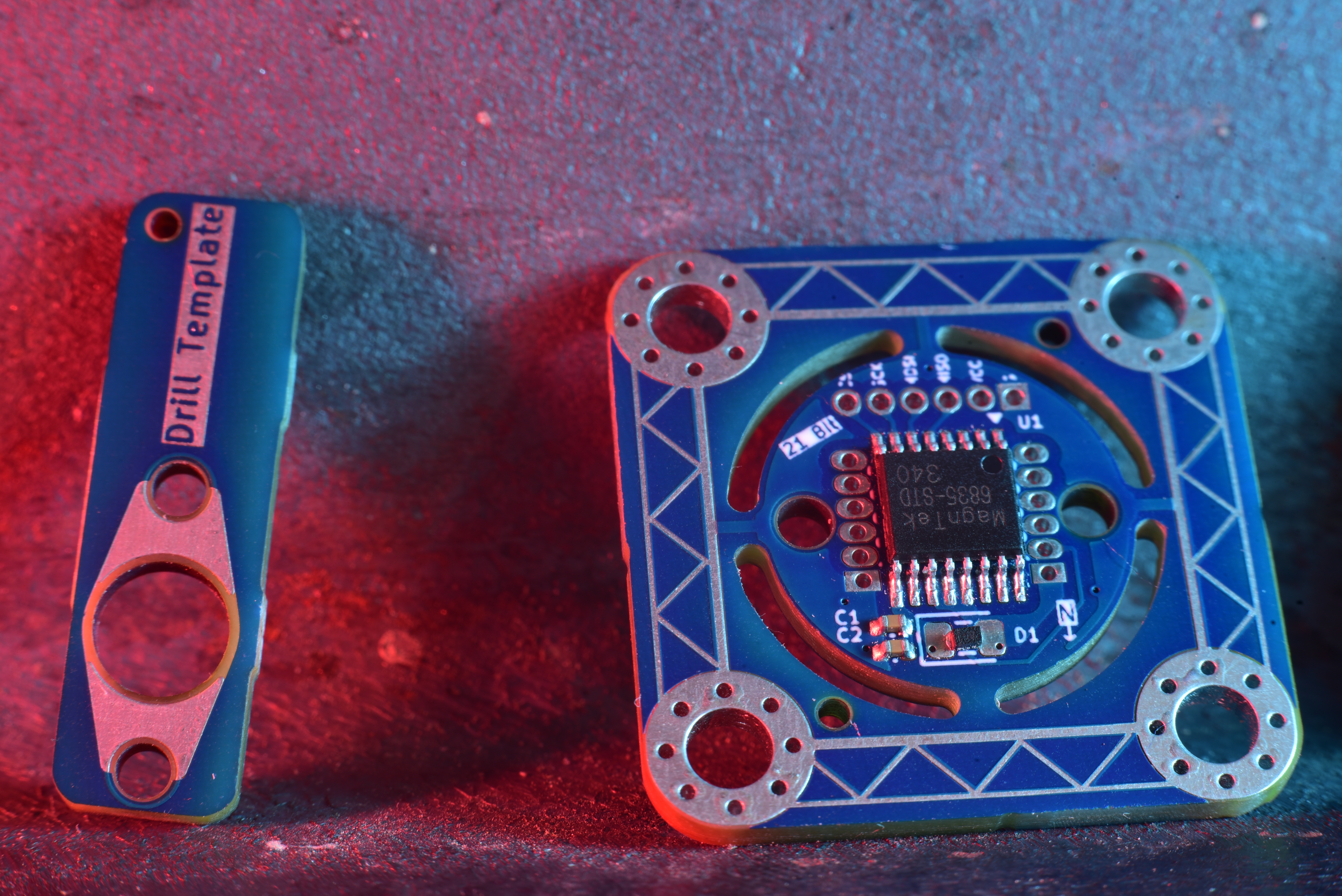 | 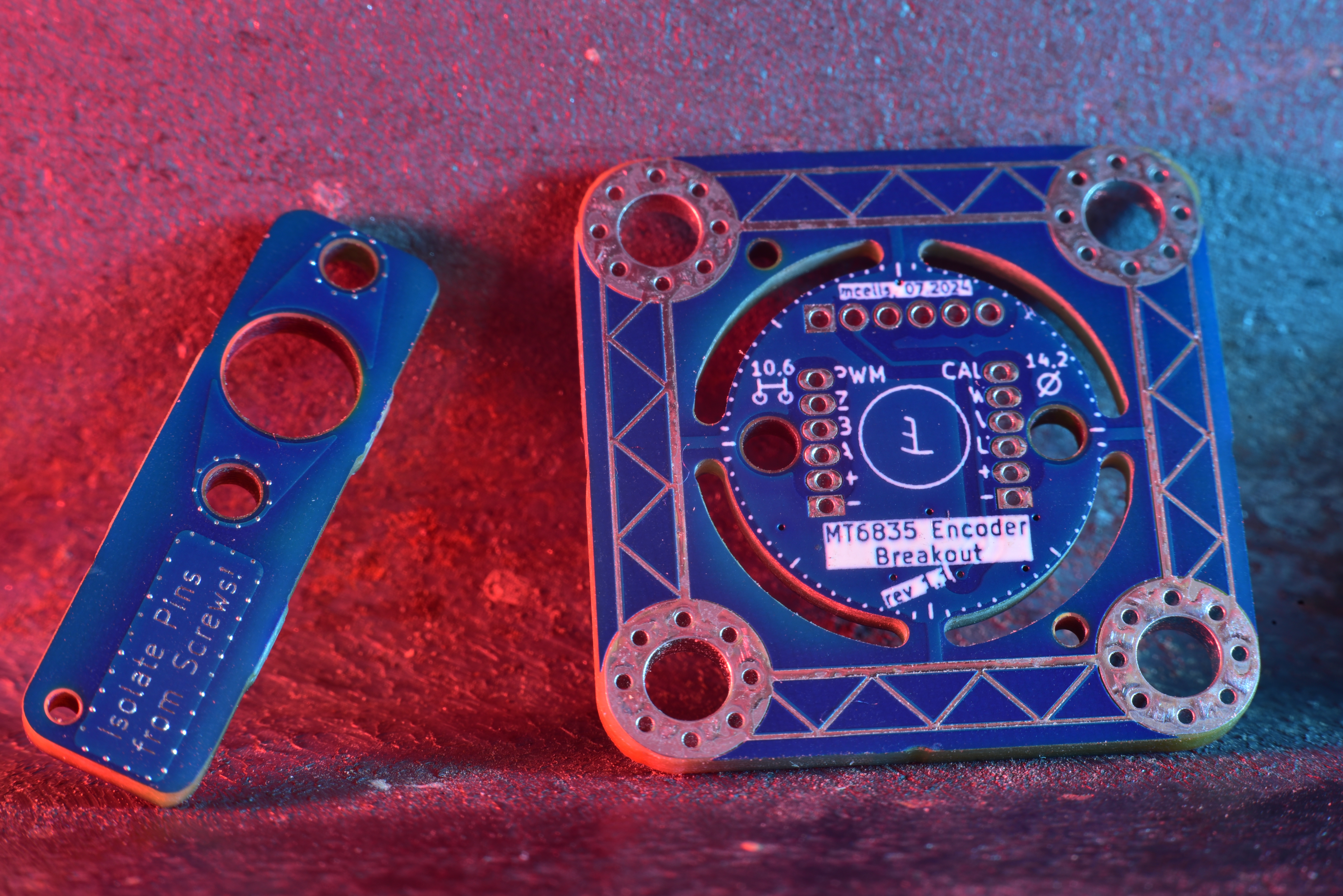 |
| Front | Back |
|---|---|
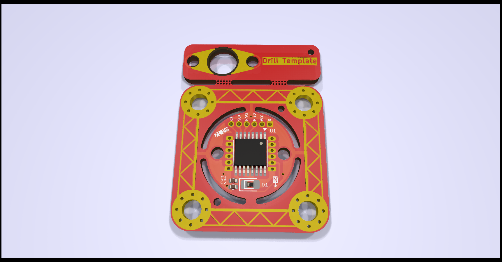 | 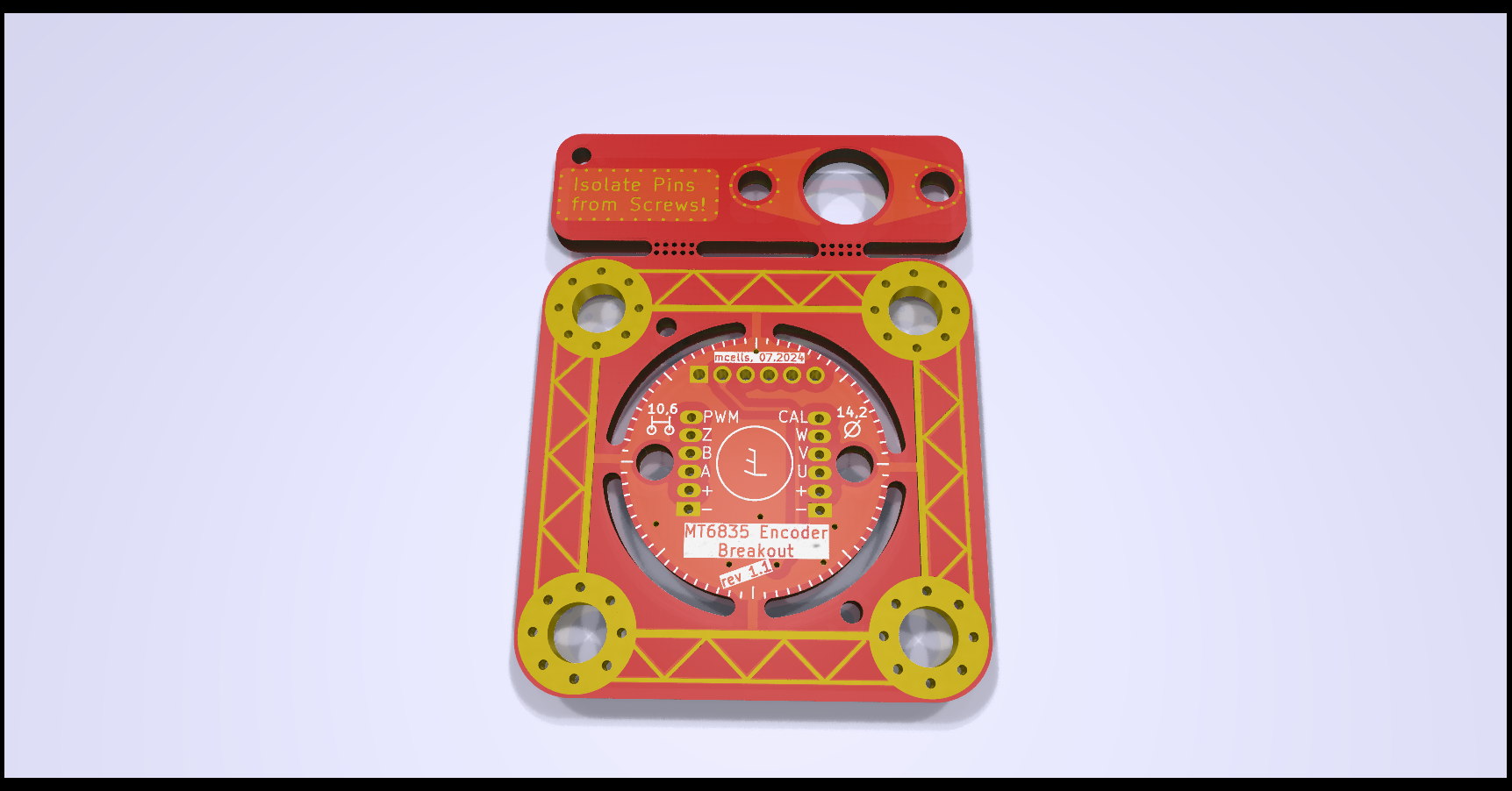 |
Installing the sensor board inside a Hoverboard motor requires you to have access to the following tools:
| Step | Image | Description |
|---|---|---|
| 1 | Disassemble the Motor, until you have just the bare Stator. Desolder and pull out all wires, so you can drill through the shaft. | |
| 2 | 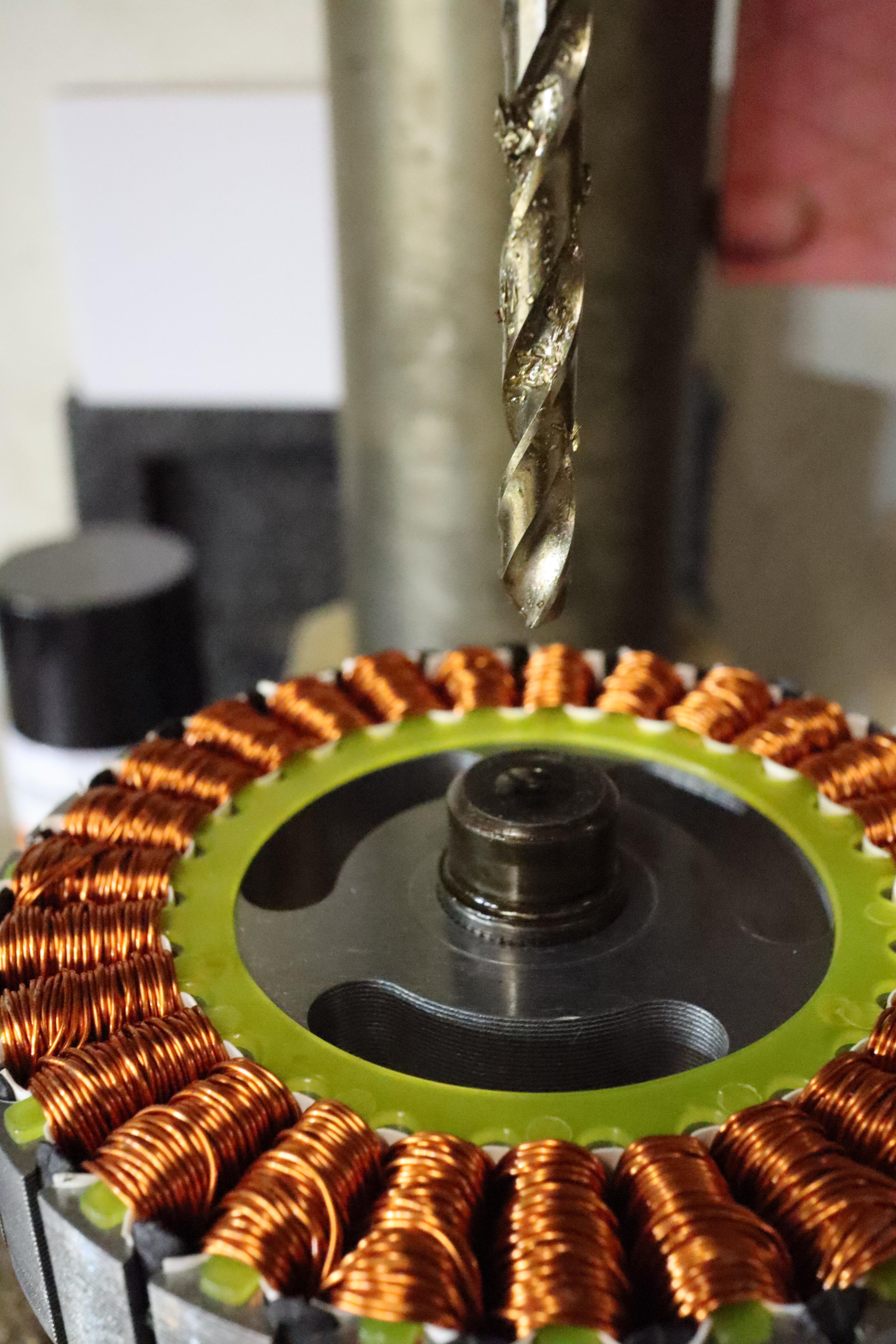 | Drill a 5mm Hole inside the top of the stator shaft. There is a centered "dimple" already in the shaft, which helps with centering the drill enormously. You want everything to be as concentric as possible, else you will get a periodic nonlinearity in the measured angle! You have to drill about 25mm until you break through to the hollow shaft. |
| 3 | 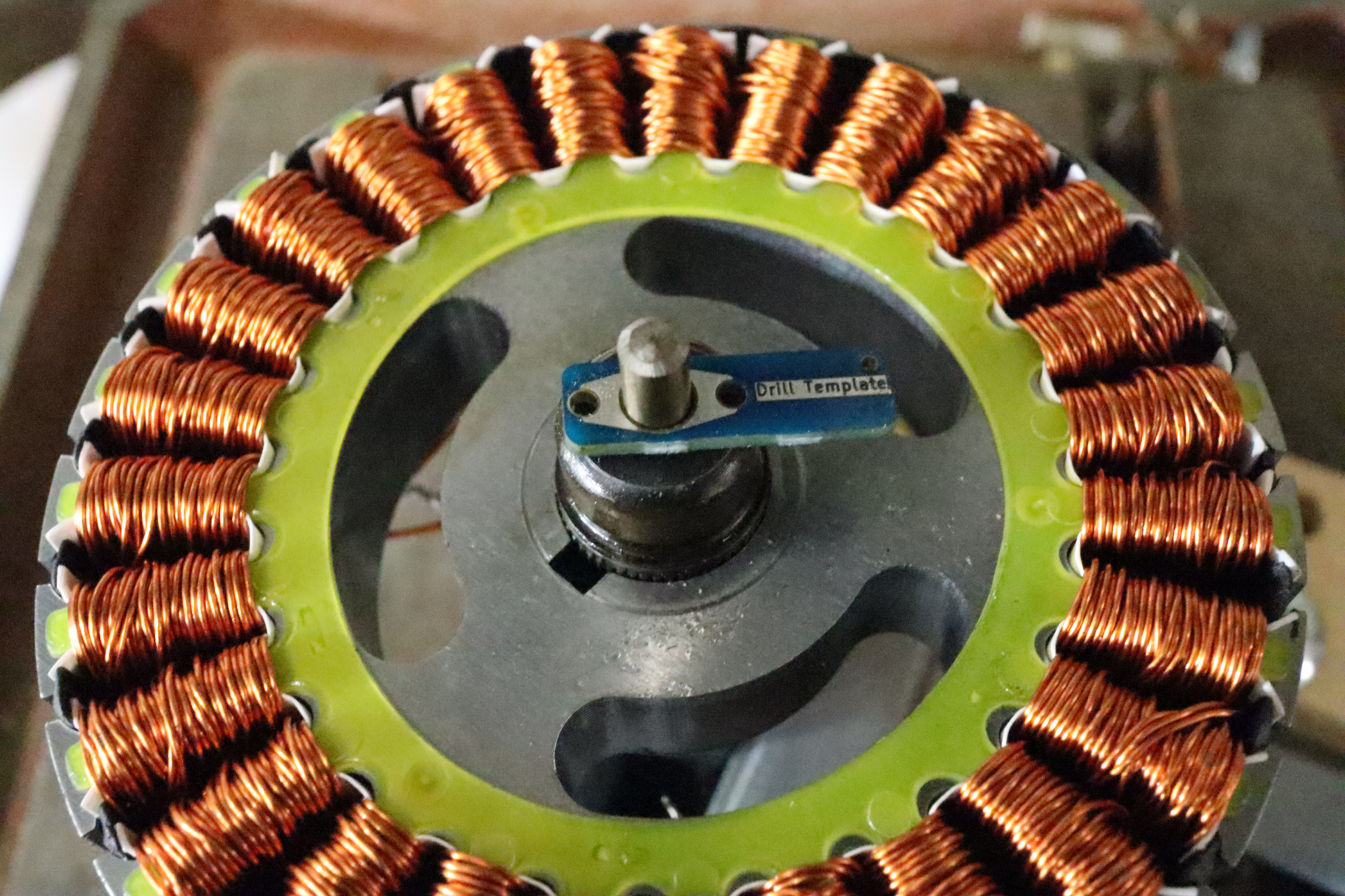 | Remove the drill bit from the drill and put it most of the way through the new hole, so that just protrudes at the top. Use the drill bit to locate the template PCB on the center of the shaft. |
| 4 | 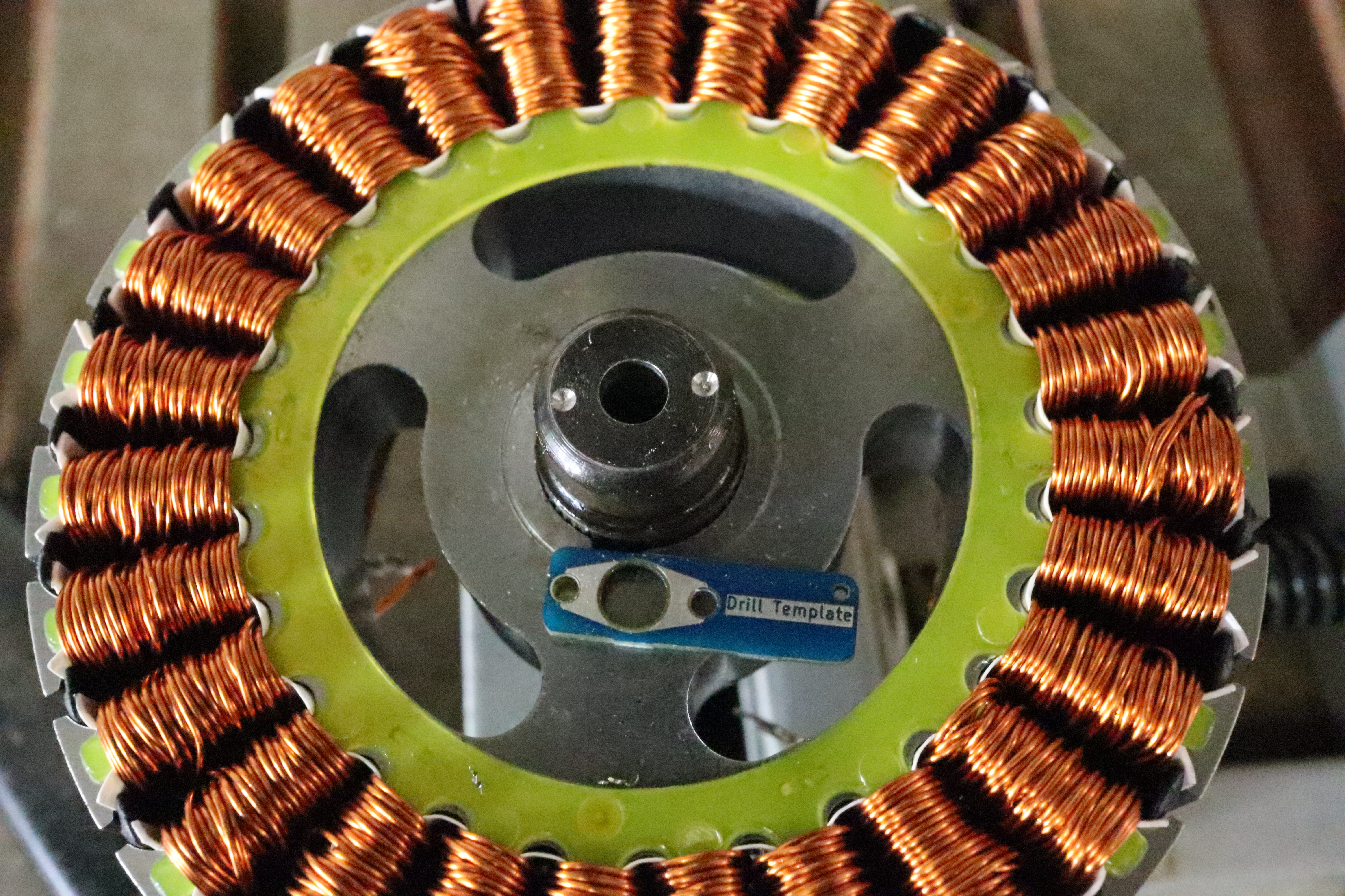 | Either use a center punch, or, using a M2 drill bit, pre drill two "dimples", so you can later locate with the smaller drill bit. When drilling the second dimple, use something like a small allen wrench in the first dimple to hold the template in place. |
| 5 | 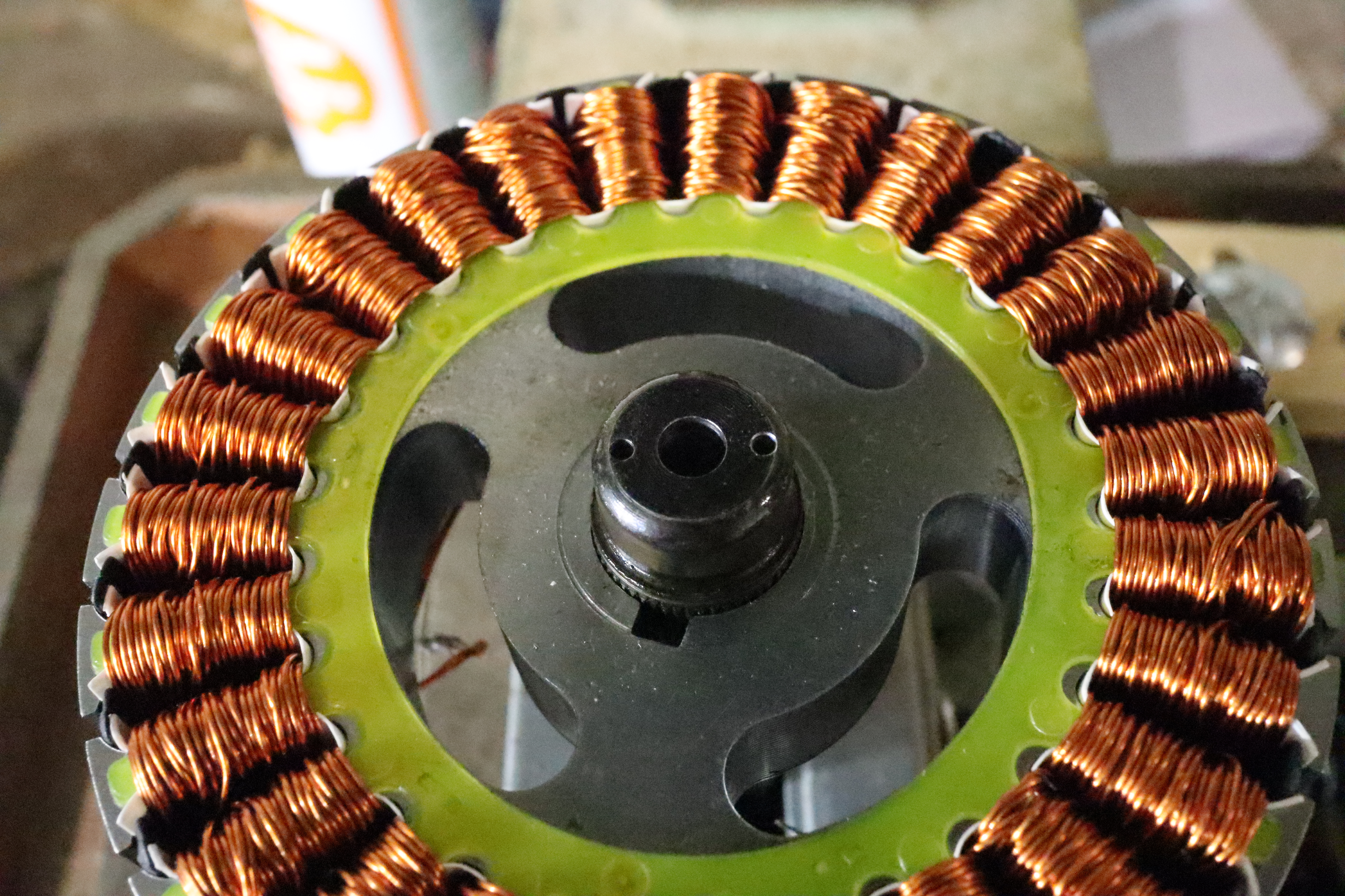 | Drill the two holes with a 1.6mm or 1.7mm bit and tap the holes to M2. You can use a 1.7mm drill to ease the tapping, as the threads don´t need to support any significant load. Also refrain from tapping more than a few mm deep, as it is absolutely not neccesary and just increases the risk of your tap snapping off. |
| 6 | 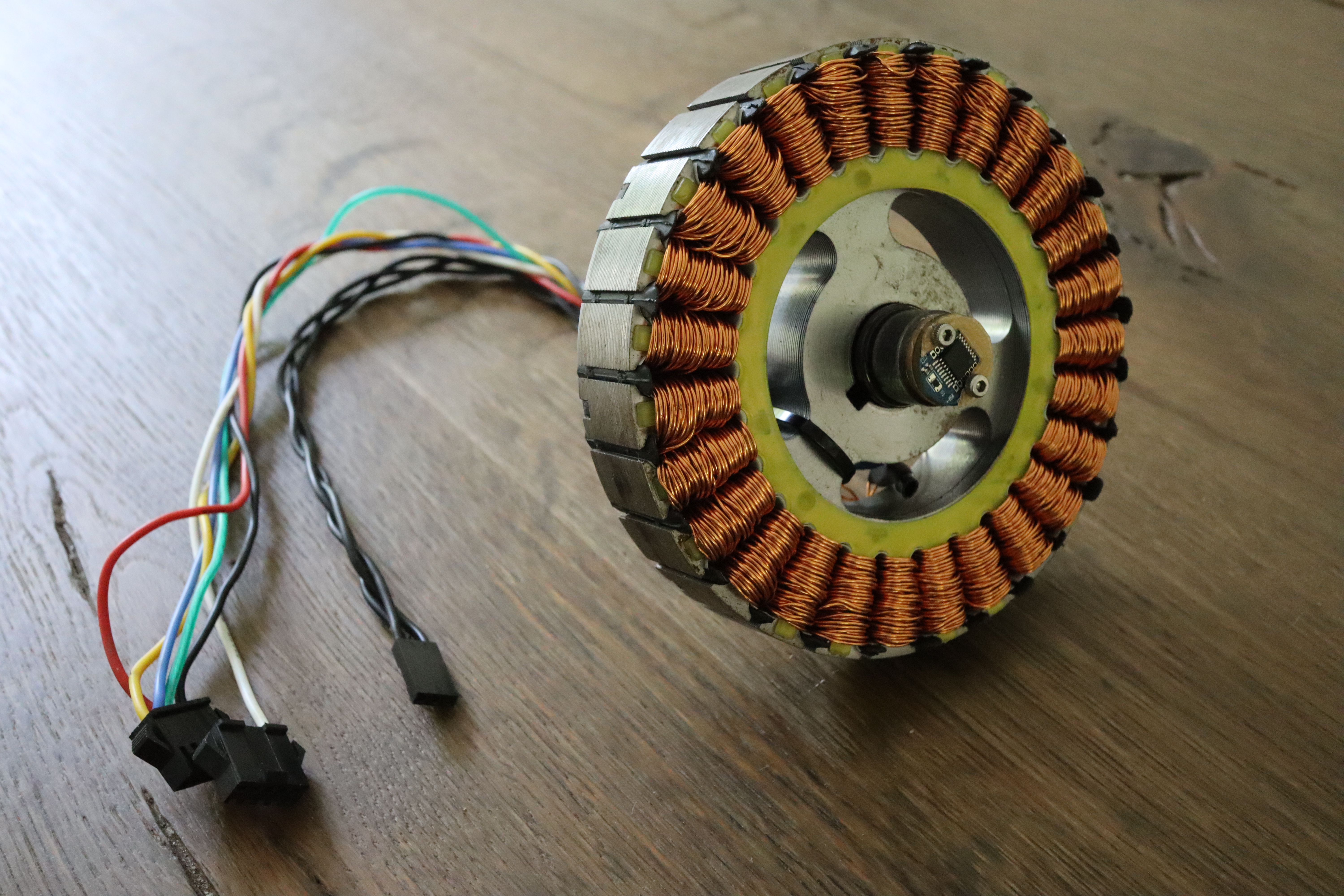 | You can now mount the sensor. Take care to use either 3d printed isolators like I did, or use plastic washers. Else you will short the sensor out! I had to drill out the 5mm hole to 6mm to make my sensor wires fit. If you have thinner wires, 5mm might be enough for you. I replaced the original wiring with new one. |
| 7 (optional) | 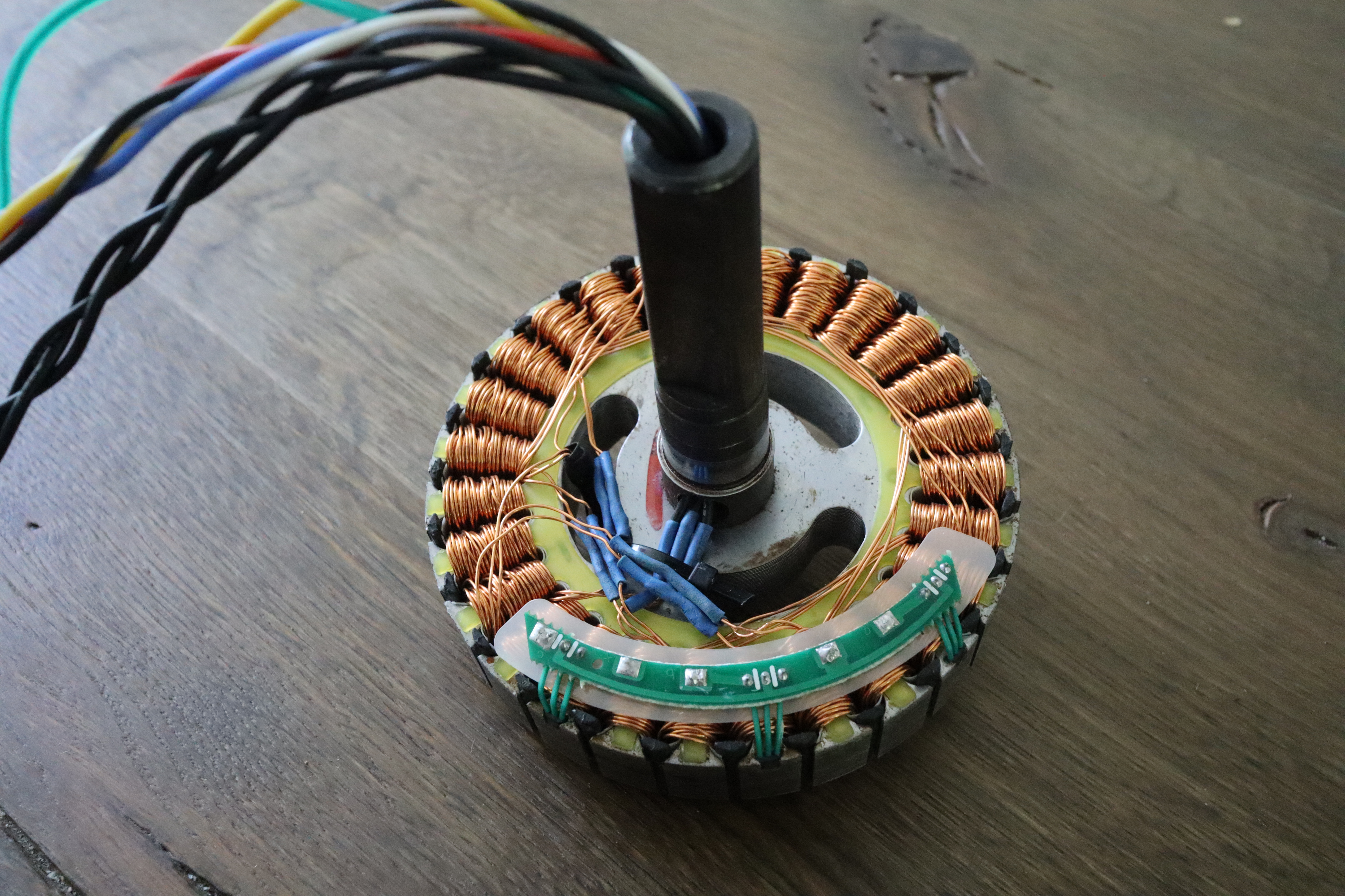 | In these motors, the 3 phases are each wound using multiple strands of enamelled copper wire, some 3, 4, or even 5 in parallel. The phases are then connected in a star, or Y topology. I wanted to lower the kV as much as possible, so I unsoldered the strands and connected them in series for each of the three phases. This lowers the kV by the number of strands you serialize, in my case three. |
| 8 | 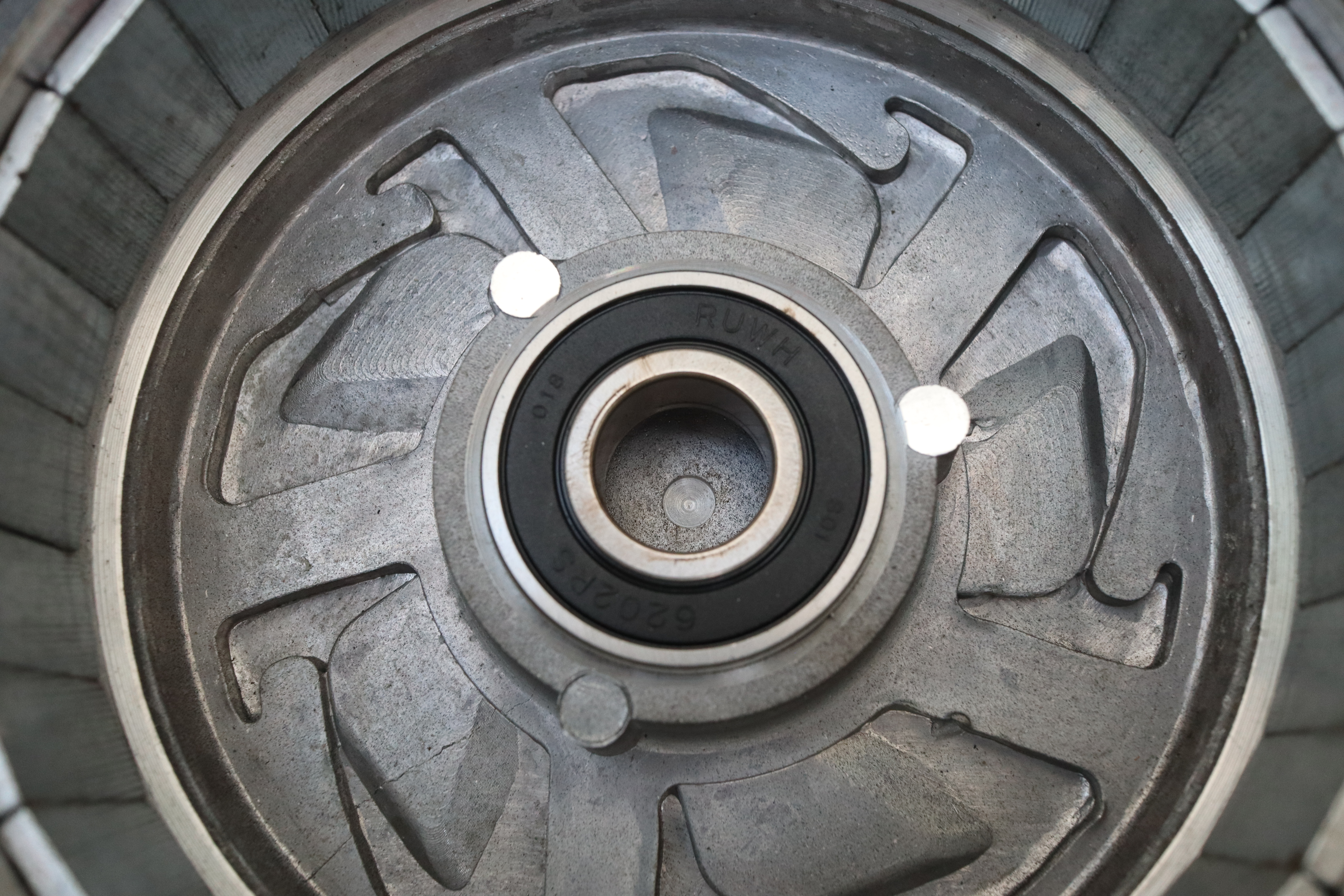 | My motors have just enough space inside, so that the magnet can be mounted directly inside the rotor bell. I marked the center of the bell by pushing a 15mm HSS drill into the bearing (15mm inside diameter) and turning the bell. This leaves a perfectly centered dimple exactly where you want to mount the magnet. The aluminium there is about 2-3mm thick. Drilling about 1mm with a drill bit of the same diameter as your magnet lets you just glue the magnet there, without drilling from the outside. |
I got my PCBs fabbed and assembled at JLC. You can use the provided KiCad project files to generate the required files. You don´t have to get assembled boards directly, as I designed the PCBs so that you can desolder the components from the aliexpress board and solder them onto this PCB. This might be far cheaper for single quantities.
If you have any questions, feel free to just create an issue/discussion or ask me on Discord (@hollowedbethyname)
| Qty | Value | Footprint | References |
|---|---|---|---|
| 2 | 0.1µF | Capacitor_SMD:C_0402_1005Metric | C1, C2 |
| 2 | PinHeader_1x06_P1.00mm_Vertical | Connector_PinHeader_1.00mm:PinHeader_1x06_P1.00mm_Vertical | J2, J3 |
| 1 | BDFN2A051U | Diode_SMD:D_SOD-882D | D1 |
| 1 | MT6835 | Package_SO:TSSOP-16_4.4x5mm_P0.65mm | U1 |
| 1 | PinHeader_1x06_P1.27mm_Vertical | Connector_PinHeader_1.27mm:PinHeader_1x06_P1.27mm_Vertical | J1 |
The 7 most common of 14 parts.
VIPQualityPost/lemon-pepper-stepper
simplefoc all-in-one 50W hybrid stepper + bldc driver

shadedvox/arsenal
A fully custom 6 degree-of-freedom robotic arm, built from the ground up across hardware, firmware, and mechanical design.


VIPQualityPost/MT6835-NEMA17
High resolution magnetic angle sensor which can be mounted to the back of NEMA17 sized stepper motors. Enables use of SPI, ABZ, UVW, and PWM outputs.

VX-wiki/non-magic-encoder
A non-magic magnetic encoder for Vectrix VX-1 maxi scooter motor controller

runger1101001/Magnetic_Encoders
Small (21x17mm) board for the SC60228 magnetic absolute angle sensor.

duwogus7650-ctrl/board-design
OpenRobot SPN-MC(=VESCular6, VESC6 파생) 동등 기능의 QDD용 원형 모터 컨트롤러를 오픈소스 VESC6를 베이스로 신규 설계하는 프로젝트.
It measures 24 × 32 mm and has 2 copper layers, 1.6 mm thick.
14 parts, built around the MT6835 and BDFN2A051U. The full list of its parts is on this page, with links to each part's symbol and footprint where PCBKit's library has them.
From the mcells/mt6835-hoverboard-motor repository on GitHub, at the commit this page was made from: the board is mt6835-hoverboard.kicad_pcb and its schematic mt6835-hoverboard.kicad_sch. PCBKit opens the board in the browser, with nothing to install.
Its repository states no licence, so its author keeps all rights: ask mcells before reusing the design.