
4 layers57 × 25.9 mm

complete bldc motor driver for drones
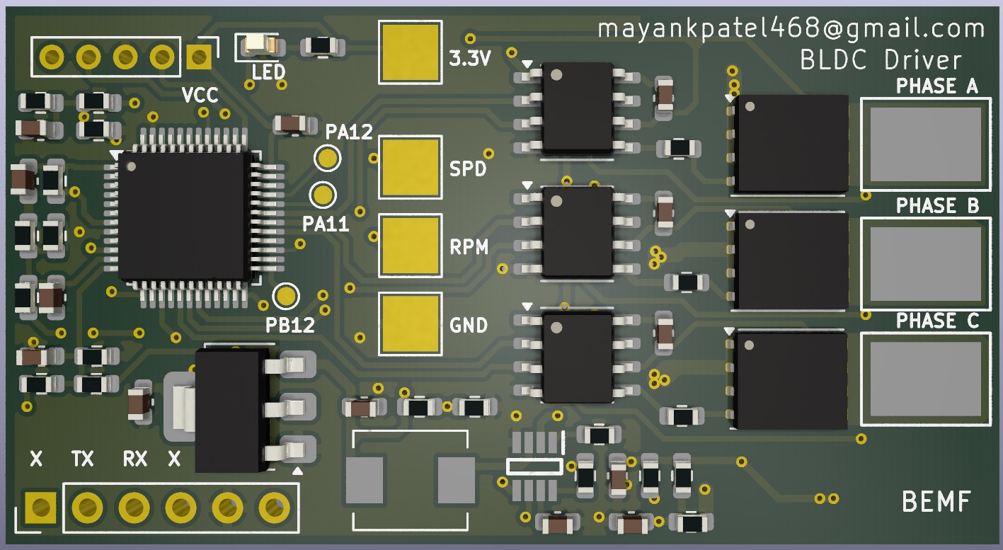
Bldc is an open-source printed circuit board by mayankpatel97, from the mayankpatel97/bldc-driver repository on GitHub. It is a 2-layer board of 54 × 29.3 mm with 74 parts on 75 nets, routed with 546 tracks and 107 vias.
It is built around the IR2101PBF, BSC13DN30NSFD and LL4148. Its parts include 27 resistors, 16 capacitors, 6 ICs, 6 transistors and 4 diodes. It belongs with the robots and motor control boards and the STM32 boards of this library.


This project is an open-source BLDC motor driver designed for drone applications. It implements a sensorless control method using Back EMF for efficient and precise motor control.
There are multiple ways to drive a BLDC motor. The three most common methods are:
Hall Sensor-Based Control
Back EMF-Based Control (Sensorless)
Power Control Mode
| Qty | Value | Footprint | References |
|---|---|---|---|
| 7 | 10uF | Capacitor_SMD:C_0603_1608Metric | C1, C2, C3, C5, C14, C16, C17 |
| 7 | 33K | Resistor_SMD:R_0603_1608Metric | R17, R19, R21, R22, R24, R25, R27 |
| 6 | 0.1uF | Capacitor_SMD:C_0603_1608Metric | C4, C9, C11, C12, C13, C15 |
| 6 | 10R | Resistor_SMD:R_0603_1608Metric | R1, R2, R3, R4, R5, R6 |
| 6 | BSC13DN30NSFD | Package_TO_SOT_SMD:TDSON-8-1 | Q1, Q2, Q7, Q8, Q9, Q10 |
| 4 | 4K7 | Resistor_SMD:R_0603_1608Metric | R9, R20, R23, R26 |
| 4 | SP | TestPoint:TestPoint_Pad_3.0x3.0mm | TP6, TP7, TP8, TP9 |
| 3 | 10K | Resistor_SMD:R_0603_1608Metric | R7, R18, R28 |
| 3 | 10nF | Capacitor_SMD:C_0603_1608Metric | C7, C8, C10 |
| 3 | C | TestPoint:TestPoint_Pad_D1.0mm | TP10, TP11, TP12 |
| 3 | IR2101 | Package_SO:SOIC-8_3.9x4.9mm_P1.27mm | U2, U3, U4 |
| 3 | LL4148 | Diode_SMD:D_MiniMELF | D1, D2, D3 |
| 2 | R_US | Resistor_SMD:R_0603_1608Metric | R12, R13 |
| 1 | 1K | Resistor_SMD:R_0603_1608Metric | R10 |
| 1 | 200K | Resistor_SMD:R_0603_1608Metric | R16 |
| 1 | 20K | Resistor_SMD:R_0603_1608Metric | R14 |
| 1 | 20R | Resistor_SMD:R_0603_1608Metric | R11 |
| 1 | 4R7 | Inductor_SMD:L_Neosid_SM-PIC0512H | L1 |
| 1 | 75K | Resistor_SMD:R_0603_1608Metric | R15 |
| 1 | A | _MAYANK:SOLDERPAD6x4 | TP1 |
| 1 | B | _MAYANK:SOLDERPAD6x4 | TP2 |
| 1 | C | _MAYANK:SOLDERPAD6x4 | TP3 |
| 1 | Conn_01x05 | Connector_PinHeader_2.00mm:PinHeader_1x05_P2.00mm_Vertical | J1 |
| 1 | Conn_01x06 | Connector_PinHeader_2.54mm:PinHeader_1x06_P2.54mm_Vertical | J3 |
| 1 | GND | _MAYANK:SOLDERPAD6x4 | TP5 |
| 1 | LD1117S33TR_SOT223 | Package_TO_SOT_SMD:SOT-223-3_TabPin2 | U1 |
| 1 | LED | LED_SMD:LED_0603_1608Metric | D4 |
| 1 | MP2315SGJ-P | _MAYANK:MP2315SGJ | IC1 |
| 1 | STM32L431CCTx | Package_QFP:LQFP-48_7x7mm_P0.5mm | U5 |
| 1 | VIN | _MAYANK:SOLDERPAD6x4 | TP4 |


phpkadir/KiCad-Sensorless-BLDC-ESC
I designed this pcb because I want to be able to try different microcontrollers as part of Electronic Speed Controller projects.

CK20000/Isolated-Half-Bridge-Driver
An isolated half-bridge motor driver board featuring 6N137 galvanic protection, an IR2101 bootstrap topology, and precise AD8418 bidirectional current sensing.


It measures 54 × 29.3 mm and has 2 copper layers, 1.6 mm thick.
74 parts, built around the IR2101PBF, BSC13DN30NSFD and LL4148. The full list of its parts is on this page, with links to each part's symbol and footprint where PCBKit's library has them.
From the mayankpatel97/bldc-driver repository on GitHub, at the commit this page was made from: the board is hw/bldc/bldc.kicad_pcb and its schematic hw/bldc/bldc.kicad_sch. PCBKit opens the board in the browser, with nothing to install.
Its repository states no licence, so its author keeps all rights: ask mayankpatel97 before reusing the design.