2 layers100 × 130.1 mm
BerlinUhr
designer2k2/BerlinUhr
Berlin Uhr or Mengenlehreuhr, a fancy retro style clock
62 parts7GPL-3.0

 MaximeZimmermann/IssaScope
Ethoscope for optogenetics behavioural essays
IssaScope v0.2 is an open-source printed circuit board by MaximeZimmermann, from the MaximeZimmermann/IssaScope repository on GitHub. It is a 2-layer board of 120 × 92.8 mm with 33 parts on 64 nets, routed with 573 tracks and 6 vias.
It is built around the LM2596S-12 and TLC5947DAP. Its parts include 17 connectors, 3 ICs, 2 capacitors, 2 resistors and 2 switches. It belongs with the ESP32 boards of this library.



This project is licensed under the GNU General Public License v3.0
The hardware is licensed under the CERN OHL v1.2
The Ethoscope consists of 15mm extruded aluminium bars purchased from MakerBeam (XL profile), and 3D printed parts.
Dedicated PCBs for all electronics components contained in the scope base and platform stimulating LEDs can be found here along with detailed instructions to reproduce and adapt them.
The PCB is built around an ESP32, a microcontroller which exchanges signals with the recording setup, and the TLC5947 LED driver, which allows linear intensity control over all stimulating lights. The microcontroller runs on C++ however, users do not need to interfere with the source code as we provide an intuitive and interactive Graphical User Interface [blocked] (GUI), from which all functions and variables can be manipulated.
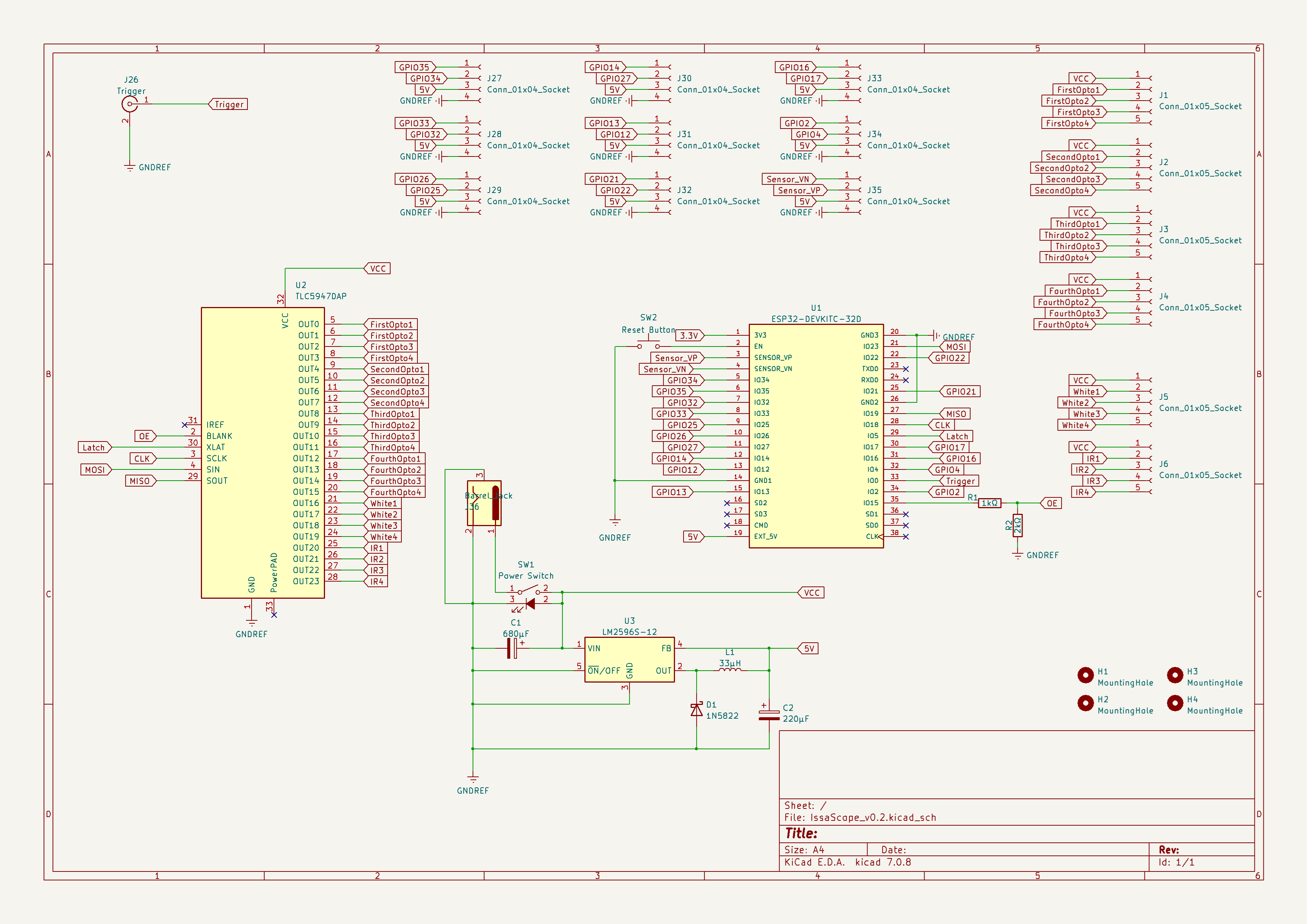
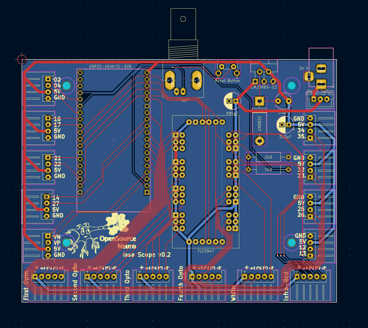
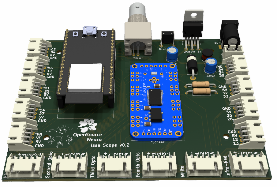
The board provides connections via Molex JST plugs for 4 * four LED channels meant to be used for 4 * four distinct optogenetics light sources.
It also provides ports for base illumination for both white and infra red lights, designed for providing light below the samples.
Remaining ports provide access to unuse GPIO pins on the microcontroller for further upgrade (I/O signals, sensors, motors, etc.)
The board takes a 24V input, a tension above this value will result in damaging the board components.
This repository contains detailed assembly instructions and an operation manual for the Scope electronics assembly. The bill of material details all components required.
To simplify the wiring assembly, a customed circuit board has been designed. PCB prototype companies (i.e. JLCPCB) will only require the gerber.zip folder to be sent to them for production.
IssaScope v0.2 firmware runs on an Espressif ESP32 board and requires the USB to UART bridge CP210x driver, which can be downloaded here.
Once the driver has been installed, users can upload and modify the microcontroller code through the Arduino IDE (Integrated Development Environment).
The ESP32 microcontroller runs a C++ code which can be accessed via the Arduino IDE, which can be downloaded here.
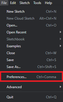
Once the IDE is installed, users needs to install the ESP32 board library:
In the Arduino IDE, go to File > Preferences
Enter the following link into the Additional Board Manager URLs field:
https://raw.githubusercontent.com/espressif/arduino-esp32/gh-pages/package_esp32_index.json
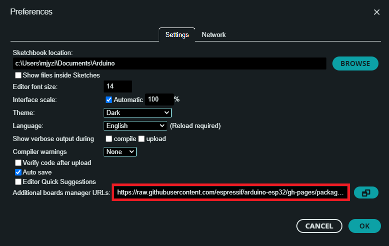 Then click on the OK button.
Next, open the Boards Manager. Go to Tools > Board > Board Manager...
Search for ESP32 and press install button for the ESP32 by Espressif Systems.
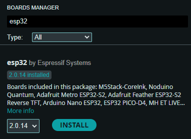 Then click on the Install button.
Finally and in a smiilar manner the library Adafruit_TLC5947 needs to be installed.
Within the Arduino IDE, user needs to select the FQBN (Fully Qualified Board Name) on which the code will be compiled for.
Here the ESP32 Dev Module needs to be selected.
Go to Tools > Board > esp32 > ESP32 Dev Module
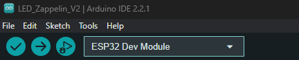 The board name should be displayed as shown.
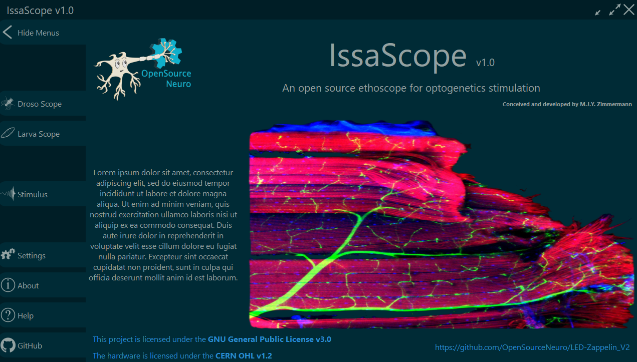
A Graphical User Interface (GUI) dedicated to this project was designed using the python PyQt6/PySide6 libraries. The entire script can be found here.
githubusercontent
The python script for the GUI can be run directly from a python environment, or run from a .exe file which can be found here [blocked]
On the main screen, Users can fi
| Qty | Value | Footprint | References |
|---|---|---|---|
| 9 | Conn_01x04_Socket | Connector_JST:JST_XH_S4B-XH-A_1x04_P2.50mm_Horizontal | J27, J28, J29, J30, J31, J32, J33, J34, J35 |
| 6 | Conn_01x05_Socket | Connector_JST:JST_XH_S5B-XH-A_1x05_P2.50mm_Horizontal | J1, J2, J3, J4, J5, J6 |
| 4 | MountingHole | MountingHole:MountingHole_3mm | H1, H2, H3, H4 |
| 1 | 1N5822 | Diode_THT:D_DO-201AD_P15.24mm_Horizontal | D1 |
| 1 | 1kΩ | Resistor_THT:R_Axial_DIN0309_L9.0mm_D3.2mm_P15.24mm_Horizontal | R1 |
| 1 | 220μF | Capacitor_THT:CP_Radial_D6.3mm_P2.50mm | C2 |
| 1 | 24 V | Connector_BarrelJack:BarrelJack_Horizontal | J36 |
| 1 | 2kΩ | Resistor_THT:R_Axial_DIN0309_L9.0mm_D3.2mm_P15.24mm_Horizontal | R2 |
| 1 | 33μH | Inductor_THT:L_Radial_D6.0mm_P4.00mm | L1 |
| 1 | 680μF | Capacitor_THT:CP_Radial_D6.3mm_P2.50mm | C1 |
| 1 | ESP32-DEVKITC-32D | Maxime:MODULE_ESP32-DEVKITC-32D | U1 |
| 1 | LM2596S-12 | Package_TO_SOT_THT:TO-220-5_P3.4x3.7mm_StaggerOdd_Lead3.8mm_Vertical | U3 |
| 1 | LOGO | Maxime:Spiky175h | G*** |
| 1 | Power Switch | Connector_JST:JST_XH_B3B-XH-A_1x03_P2.50mm_Vertical | SW1 |
| 1 | Reset Button | Button_Switch_THT:SW_Tactile_SPST_Angled_PTS645Vx39-2LFS | SW2 |
| 1 | TLC5947 | Maxime:Maxi_TLC5947 | U2 |
| 1 | Trigger | Maxime:BNC_Socket_TYCO-AMP_LargePads | J26 |
It measures 120 × 92.8 mm and has 2 copper layers, 1.6 mm thick.
33 parts, built around the LM2596S-12 and TLC5947DAP. The full list of its parts is on this page, with links to each part's symbol and footprint where PCBKit's library has them.
From the MaximeZimmermann/IssaScope repository on GitHub, at the commit this page was made from: the board is PCB/IssaScope_v0.2.kicad_pcb and its schematic PCB/IssaScope_v0.2.kicad_sch. PCBKit opens the board in the browser, with nothing to install.
Its repository states no licence, so its author keeps all rights: ask MaximeZimmermann before reusing the design.
designer2k2/BerlinUhr
Berlin Uhr or Mengenlehreuhr, a fancy retro style clock


Rob-Sligter/Smiley-LED-PCB
This repo contains my first PCB design, a smiley face board with LEDs controlled by a TLC5947 driver chip.


metalhead777/blinCAN
A 24 channel LED driver with CAN bus interface and Arduino-style microcontroller.

