2 layers75 × 119.2 mm
Stage4A
maxgr2/stage4A
Récupération du code pour mon stage puis modification du projet pour amélioration au fur et à mesure
65 parts
 maxgr2/stage4A
Récupération du code pour mon stage puis modification du projet pour amélioration au fur et à mesure
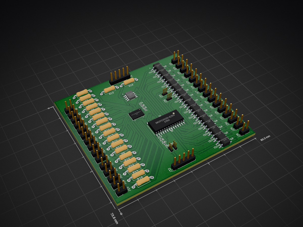
V1 cartebis is an open-source printed circuit board by maxgr2, from the maxgr2/stage4A repository on GitHub. It is a 2-layer board with 79 parts on 67 nets, routed with 519 tracks and 29 vias.
Its parts include 42 connectors, 19 resistors and 18 ICs.
Ce repo a été réalisé dans le cadre d'un stage de 4ème année d'école d'ingénieurs à l'École de Technologie Supérieure (ÉTS) de Montréal, au sein du laboratoire LACIME, par un étudiant de Polytech Grenoble. Si vous souhaitez avoir plus de détails sur le contenu de chaque projet merci de suivre les dossier projet_batterie et projet_salle_blanche. Le dossier contient aussi tous les fichiers Kicad, Le dossier Kicad contient les évolutions des différentes cartes produites et la dernière version est celle à jour pour le projet batterie. Le dossier Kicad esp maitre est le dossier principale pour le projet salle blanche.
| Qty | Value | Footprint | References |
|---|---|---|---|
| 30 | Conn_01x02_Pin | Connector_PinHeader_2.54mm:PinHeader_1x02_P2.54mm_Vertical | J2, J10, J11, J12, J13, J14, J15, J16, J17, J18, J19, J20, J21, J22, J23, J24 +14 |
| 17 | R | Resistor_THT:R_Axial_DIN0207_L6.3mm_D2.5mm_P10.16mm_Horizontal | R1, R2, R3, R4, R5, R6, R7, R8, R10, R11, R12, R13, R14, R15, R16, R17 +1 |
| 15 | ISOM11600DFGR | ESP32_Footprints:ISOM8600DFGR | U3, U4, U5, U6, U7, U8, U9, U10, U11, U12, U13, U14, U15, U16, U17 |
| 6 | Conn_01x01_Pin | Connector_PinHeader_1.00mm:PinHeader_1x01_P1.00mm_Vertical | J33, J34, J35, J40, J41, J42 |
| 4 | Conn_01x03_Pin | Connector_PinHeader_1.00mm:PinHeader_1x03_P1.00mm_Vertical | J36, J37, J38, J39 |
| 2 | 470 | Resistor_THT:R_Axial_DIN0207_L6.3mm_D2.5mm_P10.16mm_Horizontal | R18, R19 |
| 2 | Conn_01x05_Pin | Connector_PinHeader_2.54mm:PinHeader_1x05_P2.54mm_Vertical | J1, J32 |
| 1 | LTC24127CUHF-TRPBF | Esp:QFN-38_UHF_LIT | U2 |
| 1 | MCP23020-E/SO | ESP32_Footprints:MCP23017T-E&slash_SO | U1 |
| 1 | P82B715DRG4 | Esp:P82B715DRG4 | U18 |
maxgr2/stage4A
Récupération du code pour mon stage puis modification du projet pour amélioration au fur et à mesure

maxgr2/stage4A
Récupération du code pour mon stage puis modification du projet pour amélioration au fur et à mesure

maxgr2/stage4A
Récupération du code pour mon stage puis modification du projet pour amélioration au fur et à mesure

maxgr2/stage4A
Récupération du code pour mon stage puis modification du projet pour amélioration au fur et à mesure

espotek-org/Labrador
EspoTek Labrador is a USB device that transforms your PC or smartphone into a fully-featured electronics lab. This repo holds all of the source code!

hackclub/OnBoard
💡 Join 1,000 teenagers and make your first PCB with a $100 grant!

ElectronicCats/Minino
Minino is an original multiprotocol and multiband board made for sniffing, communicating, and attacking IoT devices. It was designed as a mini Cat that integrates the powerful ESP32C6, GPS, microSD and OLED.

strayer/taira-keyboard
A wireless low-profile split mechanical keyboard with 66 keys inspired by the ErgoDash and Corne Chocolate


cnlohr/cnhardware
My dumping grounds for all my kicad projects and random hardware bringup.

79 parts. The full list of its parts is on this page, with links to each part's symbol and footprint where PCBKit's library has them.
From the maxgr2/stage4A repository on GitHub, at the commit this page was made from: the board is Kicad/V1_cartebis/V1_cartebis.kicad_pcb and its schematic Kicad/V1_cartebis/Temp_board_ajout.kicad_sch. PCBKit opens the board in the browser, with nothing to install.
Its repository states no licence, so its author keeps all rights: ask maxgr2 before reusing the design.