2 layers59.5 × 40 mm

 Maxandersen1/ESP32-S3-Flight_Controller
Custom ESP32 Flight Controller using BMI088 & BMP388 sensors. Hardware and firmware built from the ground up.
ESP32 Flight Conroller is an open-source printed circuit board by Maxandersen1, from the Maxandersen1/ESP32-S3-Flight_Controller repository on GitHub, published under the MIT licence. It is a 4-layer board of 40.5 × 48.8 mm with 52 parts on 63 nets, routed with 504 tracks and 72 vias.
It is built around the ESP32-S3-WROOM-1-N8, BMP388 and TPS54331DG4, with the AMS1117-3.3, BMI088 and USBLC6-2SC6 among its other parts. Its parts include 17 capacitors, 15 resistors, 6 ICs, 4 connectors and 3 diodes. It belongs with the robots and motor control and sensors and measurement boards and the ESP32 boards of this library.


A custom-designed drone flight controller built from the ground up around the ESP32-S3 microcontroller. This project is a work-in-progress, covering everything from custom PCB design in KiCad to low-level sensor drivers and Web Serial 3D visualization.
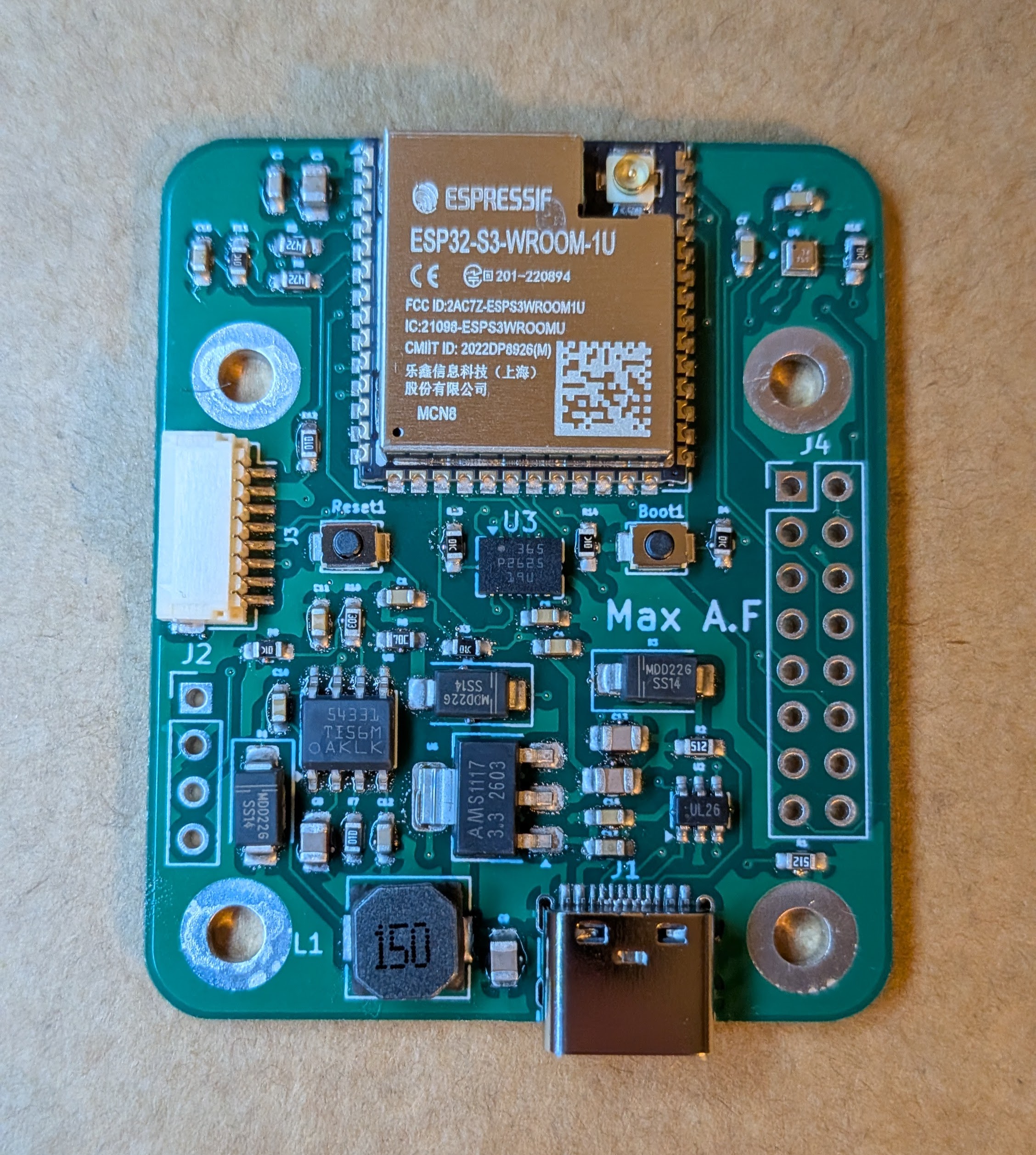
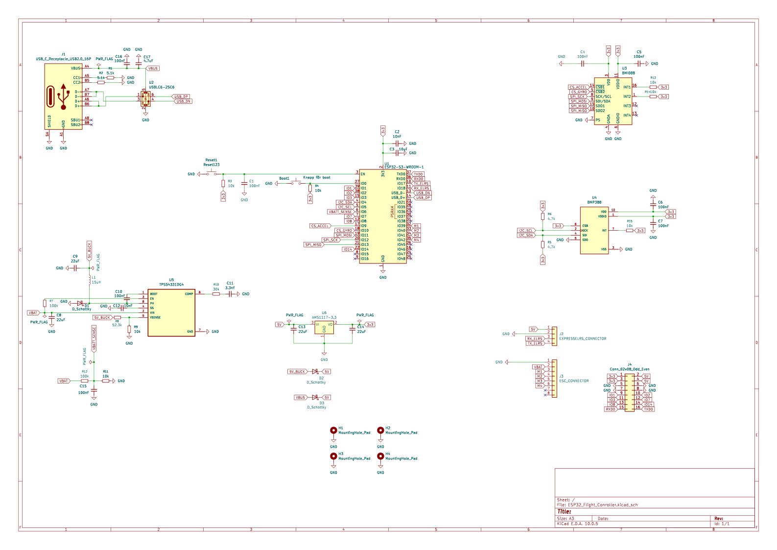
The schematic was designed in KiCad and ordered as a 4-layer PCB from JLCPCB.
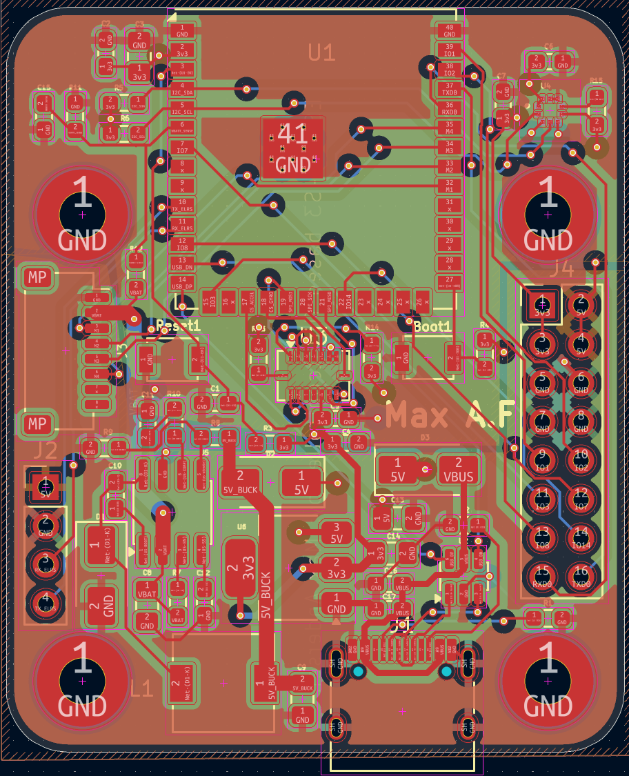
The layout was routed in KiCad with the following dedicated 4-layer stackup:
| Designator | Component / Part | Package | Qty | Function |
|---|---|---|---|---|
| U1 | ESP32-S3-WROOM-1 | SMD Module | 1 | Main Flight Controller MCU |
| U3 | Bosch BMI088 | LGA-16 | 1 | 6-Axis IMU (SPI) |
| U4 | Bosch BMP388 | LGA-10 | 1 | Barometric Pressure & Altitude Sensor (I2C) |
| U5 | TI TPS54331DG4 | SOIC-8 | 1 | Step-Down Buck Converter (Battery Vin to 5V) |
| U6 | AMS1117-3.3 | SOT-223 | 1 | Low-Dropout (LDO) Linear Voltage Regulator (3.3V) |
| U2 | USBLC6-2SC6 | SOT-23-6 | 1 | Low-Capacitance ESD Protection Array (USB) |
| D1, D2, D3 | SS14 / SS34 | SMA (DO-214AC) | 3 | Schottky Barrier Diodes |
| L1 | 15 µH (e.g. LVS606020) | SMD (~6x6 mm) | 1 | Power Inductor for Buck Converter |
| Designator | Description | Qty | Function |
|---|---|---|---|
| J1 | USB-C 12-pin (TYPE-C-31-M-12) | 1 | USB Data / Programming & 5V Power |
| J3 | JST-SH 8-Pin SMD (SM08B-SRSS-TB) | 1 | 4-in-1 ESC Interconnect (PWM / DSHOT signals) |
| J2, J4 | 2.54mm Pitch Pin Headers | 2 | RC Receiver (UART) & Expansion / Debug pins |
| SW1, SW2 | SMD Tactile Push Buttons | 2 | Bootloader & Hardware Reset |
100 nF (0603) — 8 pcs (Decoupling for MCU, sensors, and regulators)10 nF (0603) — 2 pcs (Noise filtering / compensation)3.3 nF (0603) — 1 pc (Buck converter compensation loop)4.7 µF (0603) — 1 pc (Bulk decoupling)10 µF (0805) — 1 pc (LDO input/output stabilization)22 µF (0805) — 4 pcs (High-capacitance power rail smoothing)10 kΩ — 7 pcs (Pull-ups & boot mode configuration)4.7 kΩ — 2 pcs (I2C bus pull-ups for SDA / SCL)5.1 kΩ — 2 pcs (USB-C CC line pull-downs for 5V power negotiation)100 kΩ — 2 pcs (Voltage dividers & enable lines)30 kΩ — 1 pc (Feedback network)52.3 kΩ — 1 pc (High-precision feedback resistor for buck regulator)The firmware is written in C++ (Arduino framework) and features:
Included in the tools/ directory is a custom HTML5/Three.js 3D drone visualizer.
It uses the modern Web Serial API to connect directly to the flight controller via USB (no servers required) and renders the drone's orientation in real-time at 60fps based on the live IMU telemetry.
hardware/: KiCad schematics and PCB layout files.firmware/FlightController/: The main C++ Arduino sketch containing sensor drivers and mathematical filters.tools/: Contains 3D_Viewer.html (Double-click to open in a modern browser).Hardware designed from scratch by Max. Firmware and 3D visualization developed using AI-assisted pair programming.
| Qty | Value | Footprint | References |
|---|---|---|---|
| 8 | 100nF | Capacitor_SMD:C_0603_1608Metric_Pad1.08x0.95mm_HandSolder | C1, C4, C5, C6, C7, C10, C15, C16 |
| 7 | 10k | Resistor_SMD:R_0603_1608Metric_Pad0.98x0.95mm_HandSolder | R3, R4, R9, R11, R13, R14, R15 |
| 4 | 22uF | Capacitor_SMD:C_0805_2012Metric_Pad1.18x1.45mm_HandSolder | C8, C9, C13, C14 |
| 4 | MountingHole_Pad | MountingHole:MountingHole_3mm_Pad | H1, H2, H3, H4 |
| 3 | D_Schottky | Diode_SMD:D_SMA | D1, D2, D3 |
| 2 | 100k | Resistor_SMD:R_0603_1608Metric_Pad0.98x0.95mm_HandSolder | R7, R12 |
| 2 | 10nF | Capacitor_SMD:C_0603_1608Metric_Pad1.08x0.95mm_HandSolder | C2, C12 |
| 2 | 4.7k | Resistor_SMD:R_0603_1608Metric_Pad0.98x0.95mm_HandSolder | R5, R6 |
| 2 | 5.1k | Resistor_SMD:R_0603_1608Metric_Pad0.98x0.95mm_HandSolder | R1, R2 |
| 1 | 10uF | Capacitor_SMD:C_0805_2012Metric_Pad1.18x1.45mm_HandSolder | C3 |
| 1 | 15uH | Inductor_SMD:L_6.3x6.3_H3 | L1 |
| 1 | 3.3nF | Capacitor_SMD:C_0603_1608Metric_Pad1.08x0.95mm_HandSolder | C11 |
| 1 | 30k | Resistor_SMD:R_0603_1608Metric_Pad0.98x0.95mm_HandSolder | R10 |
| 1 | 4.7uF | Capacitor_SMD:C_0603_1608Metric_Pad1.08x0.95mm_HandSolder | C17 |
| 1 | 52.3k | Resistor_SMD:R_0603_1608Metric_Pad0.98x0.95mm_HandSolder | R8 |
| 1 | AMS1117-3.3 | Package_TO_SOT_SMD:SOT-223-3_TabPin2 | U6 |
| 1 | BMI088 | Package_LGA:Bosch_LGA-16_4.5x3mm_P0.5mm_LayoutBorder7x1y_ClockwisePinNumbering | U3 |
| 1 | BMP388 | BMP388:XDCR_BMP388 | U4 |
| 1 | Conn_02x08_Odd_Even | Connector_PinHeader_2.54mm:PinHeader_2x08_P2.54mm_Vertical | J4 |
| 1 | ESC_CONNECTOR | Connector_JST:JST_SH_SM08B-SRSS-TB_1x08-1MP_P1.00mm_Horizontal | J3 |
| 1 | ESP32-S3-WROOM-1 | RF_Module:ESP32-S3-WROOM-1U | U1 |
| 1 | EXPRESSELRS_CONNECTOR | Connector_PinHeader_2.54mm:PinHeader_1x04_P2.54mm_Vertical | J2 |
| 1 | Knapp för boot | Button_Switch_SMD:SW_SPST_B3U-1000P | Boot1 |
| 1 | Reset123 | Button_Switch_SMD:SW_SPST_B3U-1000P | Reset1 |
| 1 | TPS54331DG4 | Package_SO:SOIC-8_3.9x4.9mm_P1.27mm | U5 |
| 1 | USBLC6-2SC6 | Package_TO_SOT_SMD:SOT-23-6 | U2 |
| 1 | USB_C_Receptacle_USB2.0_16P | Connector_USB:USB_C_Receptacle_HRO_TYPE-C-31-M-12 | J1 |
It measures 40.5 × 48.8 mm and has 4 copper layers, 1.6 mm thick.
52 parts, built around the ESP32-S3-WROOM-1-N8, BMP388, TPS54331DG4 and AMS1117-3.3. The full list of its parts is on this page, with links to each part's symbol and footprint where PCBKit's library has them.
From the Maxandersen1/ESP32-S3-Flight_Controller repository on GitHub, at the commit this page was made from: the board is hardware/ESP32_Flight_Conroller.kicad_pcb and its schematic hardware/ESP32_Flight_Conroller.kicad_sch. PCBKit opens the board in the browser, with nothing to install.
Its repository publishes it under the MIT licence: you may reuse it on that licence's terms (keep the author's notice, and for a copyleft licence share your changes alike).


GrozaMihaiRoland/Proiect-Drona-QuadCopter-Drona-Dumitru
Documentatia si rezumatul proiectului

SzymonLy/Quadcopter_2.1
Projekt PCB do autonomicznego quadcoptera, wersja finalna i sprawna

matveylapin/CopterCat_cm4
Полётный контроллер для стандарта FMU-v6u. Обычно на дронах для программирования устанавливают полётный контроллер, одноплатный компьютер и иногда arduino.

rland93/ollyfc
A small rust-embedded flight computer. RTIC, FrSky protocols, and STM32F4 hardware.


OmkarKnkr/Atlas-S3-DevBoard
Atlas S3 DevBoard is a custom ESP32-S3 development board designed from the ground up with an emphasis on compactness, usability, and clean PCB design practices.