
2 layers21.1 × 26.9 mm

 mattwach/game_controller_latency_tester1
A hardware design and some software tools for measuring the latency of game controllers with a Raspberry PI
Latency schematic is an open-source printed circuit board by mattwach, from the mattwach/game_controller_latency_tester repository on GitHub. It is a 2-layer board of 58.4 × 27.3 mm with 13 parts on 47 nets, routed with 37 tracks and 0 vias.
It is built around the BS170. Its parts include 8 resistors, 3 connectors and 2 transistors. It belongs with the keyboards and input boards of this library.
This project provides a (couple of) hardware designs for interfacing a game controller to a Raspberry PI (or similar) and automatically measuring the input latency added by the controller.
The "input latency" I'm referring to in this document is the amount of time that passes between a button being pressed on the controller and application (game) receiving the event.
This is the sum of all of the following:
"button" could also mean deflecting a stick.
Some setups, such as this one use microcontroller hardware to handle #1, #3 and #4. This project uses a Raspberry PI instead.
One reason to use a microcontroller is more control over the environment. A Raspberry PI running Linux could get interrupted in the middle of a measurement which would unfairly penalize the result. That said, the PI has many advantages as well:
If Raspberry PI's are still hard to find, there are many alternative options. The needed requirements are GPIO support and USB. You could use a generic PC with a USB to GPIO converter to send the needed trigger signals. Something like this or make-your-own with a PI Pico.
Not using a Raspberry pi will likely require some tweaks to the source code provided in this project.
So in the text below, you can replace "Raspberry PI" with whatever you hapen to be using.
1-4 repeats many time (1000 or more) to build up statistics.
One test pattern would be to toggle the GPIOs very fast, like 1000 times per second. But since no human player could ever do this, it could be argued that poor results in these setups might not be represent a real-world experience.
The test programs in this project try to set up a more "real world" situation but toggling two GPIO channels at 10Hz (or 20 inputs per second). The way this is implemented is to toggle GPIO1 every 100ms and GPIO2 every 98ms. This creates a pattern that looks like this:
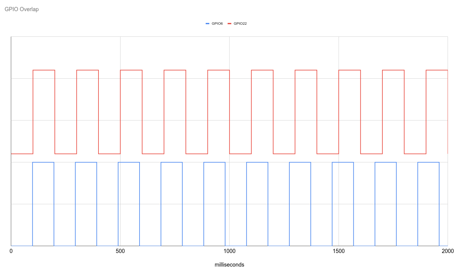
The game controller thus has to sometimes handle button being pressed at the same time as could sometimes happen in real use.
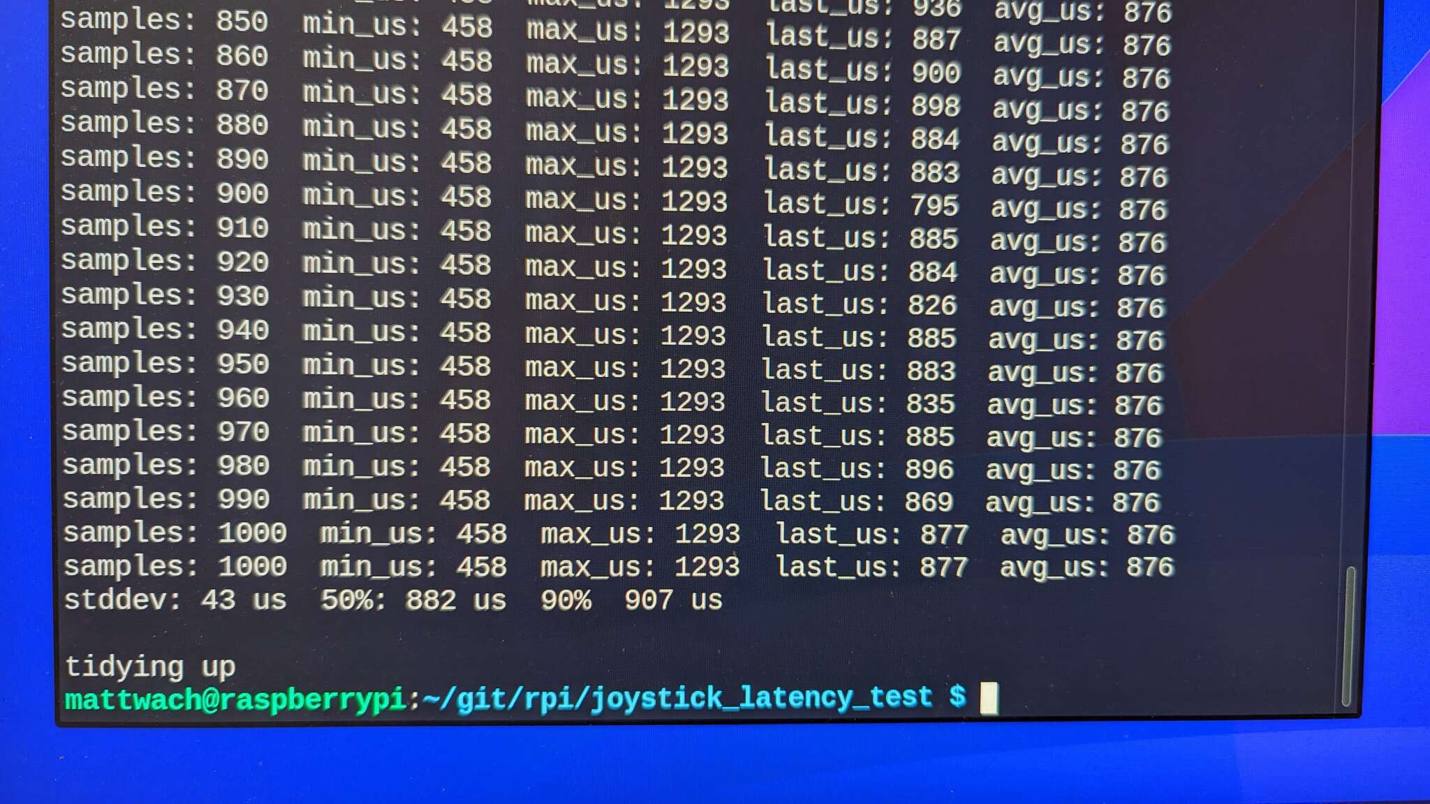
The image above shows output statistics from simple_latency_test and the
GP2040 firmware, which has excellent
performance.
The reported statistics will be as follows:
At 60 Hz, a video frame is (around 16ms). So if your controller latency is > 16ms, then you will lose a frame due to the controller every time. If your latency is 8ms, you will lose a frame about half the time, and so on.
As far as how important a missed frame is, I invite you to draw your own conclusions. But here are some sources:
This reaction time test shows humans to be around 200ms on average.
But there is more to gaming that pure reaction. Most games offer "cues" or "tells" that are followed by predictable patterns. Some games are fully predictable, like playing a song. When events can be predicted and tracked, it becomes less about reaction time and more about "temporal precision". This particular study measured temporal precision at just 6ms for some activities.
So it depends on many things but the studies above suggset there are cases where low latency "matters" in terms of giving a player an additional advantage at some games.
Let's start with the most straight-forward hardware approach. You could directly connect a PI GPIO to a controller and in many cases it will work, but there are risks:
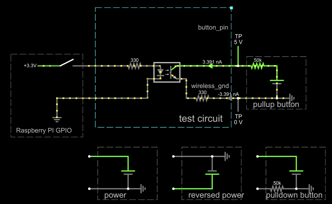
Thus I suggest using protection circuitry to keep the PI and controller isolated from each other and reduce the risks of damage. I present two protection designs: optocoupler based, and NFET based.
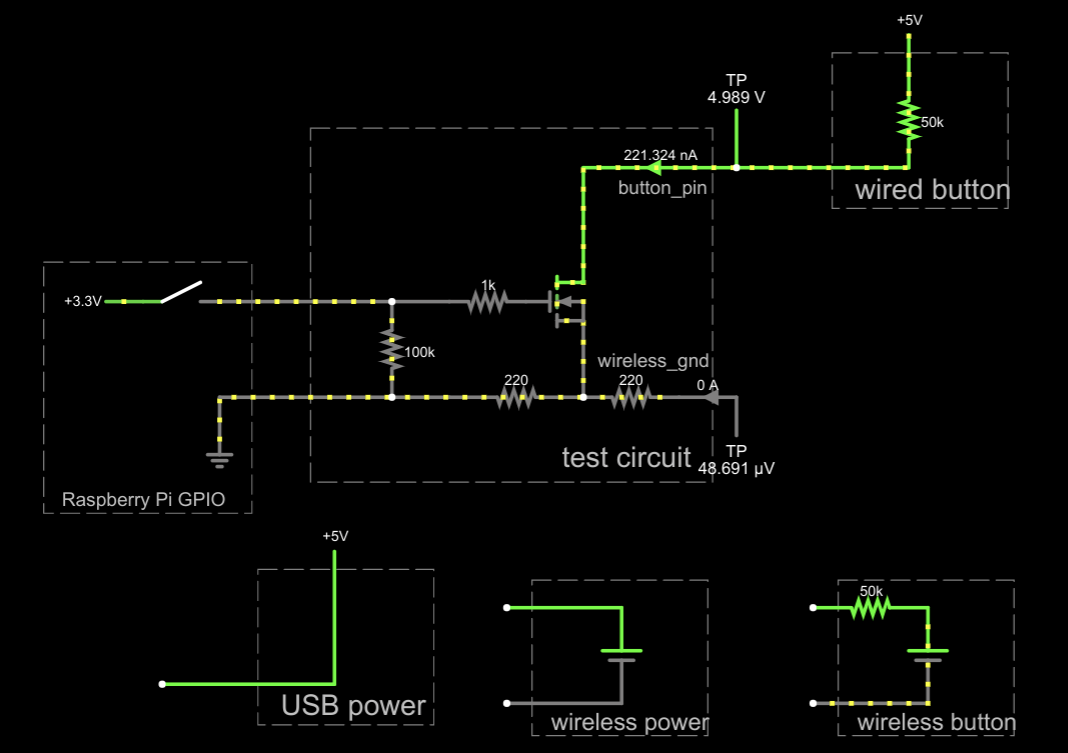
The NFET design has the advantage of easier hookup and faster operation. The disadvantage is that it will only work with "pull up resistor" style buttons. If you unknowingly hook it to something else by mistake, no damage will occur but the test will not be able to execute. Pullup configurations are more commonly used in design but some designs may have reasons (or arbitrarily) decided to implement their buttons dfferently.
Another advantage of the FET, assumed pull up configuration is that the USB cable (on USB controllers) can be used as the ground connection for the test - this simplifies wiring and eliminates some types of wiring errors.
The optocoupler based design will work with either pull up or pull down configuratons, but you need to known which way the current flows through the button and connect two wires per button. Getting any of this wrong should not do any damage, but the test will fail to execute. Optocouplers are also quite a bit slower than FETs. The one I had on-hand took around 2us to activate and 100+us to turn itself off. You can get faster ones, but need to look at the datasheet when you pick one. In comparison, FET's just take a handful of ns to turn on/off.
Going forward, I'll assume we are going with the NFET design. If you need the optocoupler one, then your hardware build will be different but the software you run will be the same.
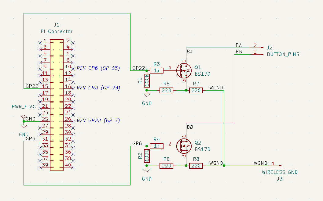
In the latency_schematic/ directory, I put together a schematic of the NFET design:
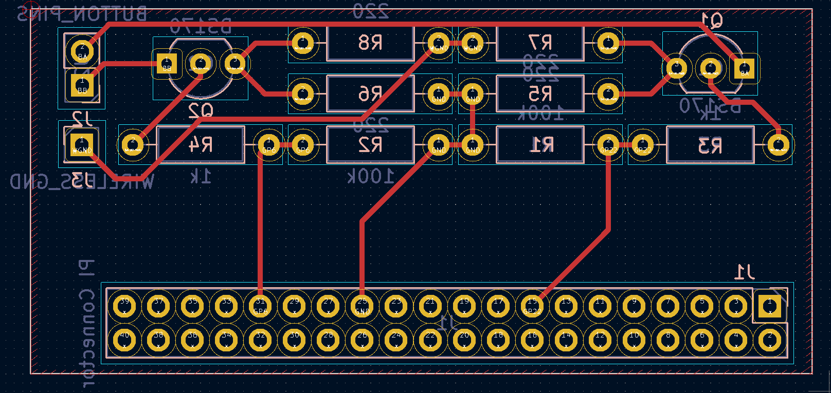
As well as a PCB layout that you can hand-wire, CNC cut, chemical etch or send to a fab.
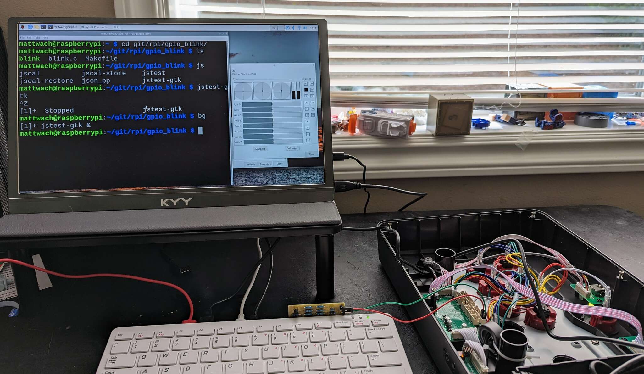
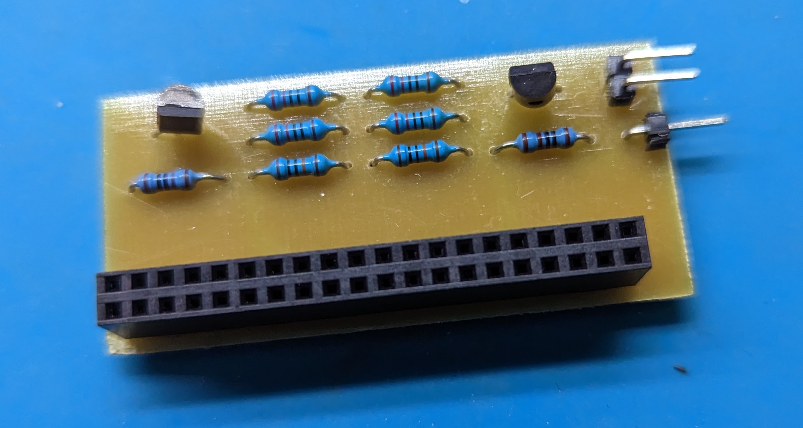
Here is my finished hardware:
Here is the hardware connected to a Mayflash F500 arcade stick:
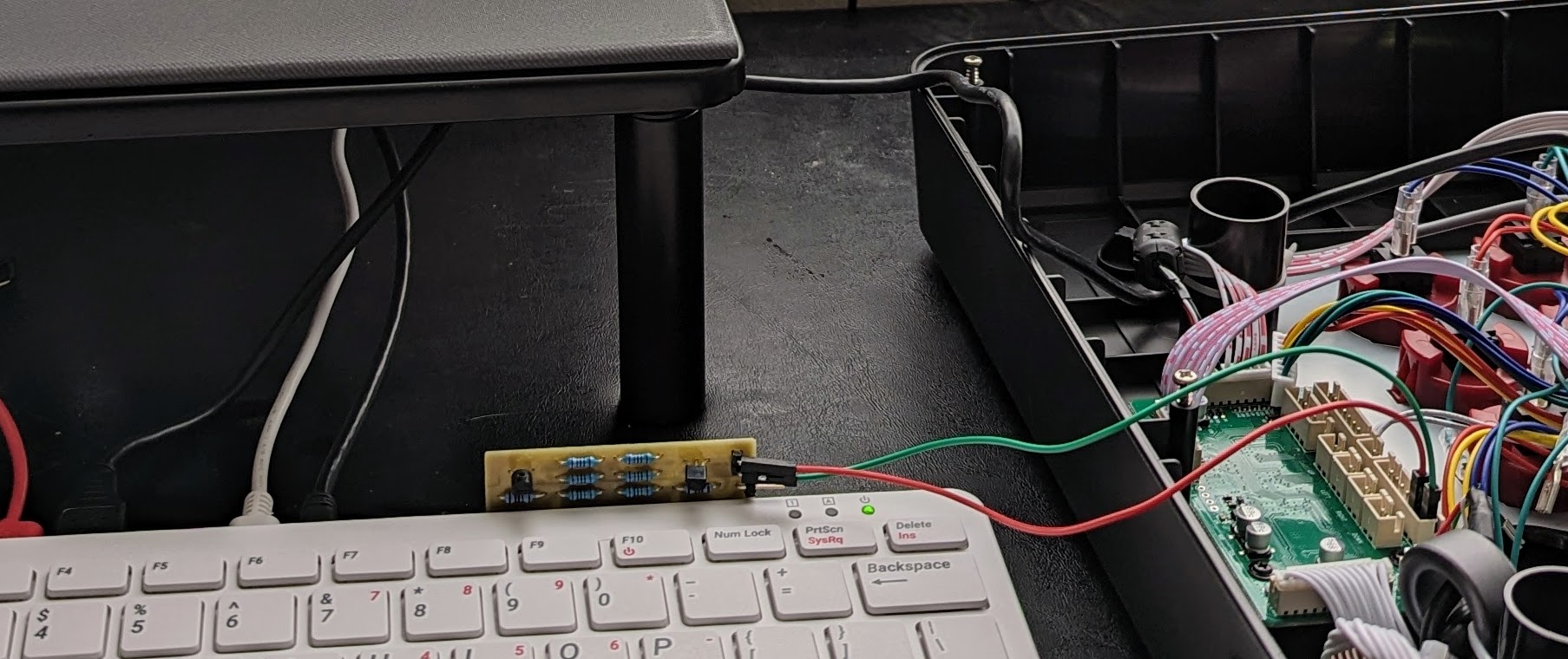
One wire for each GPIO. There is no need to connect a ground wire in this case because there is a ground connection from the USB connection. If this were a wireless controller, then the additional ground wire would need to be connected.
Most of the tools you will build as a part of this project. The process is to type
makeThe standard Raspberry PI image should already contain the dependencies that you will need.
This is a commonly-availabe tool. e.g. in Ubuntu you can just say
sudo apt install jstest-gtkto install the software. This software can be used to verify that your controller is connected and working. It can also tell you the device number (which is often /dev/input/js0 if you only have one connected).
This tool was built when you executed make. You run it like this
./toggle_testThe test simply toggles GPIO6 and GPIO22 every second. If you have jstest-gtk running and the hardware all hooked up, you will ideally see the software reporting that buttons are being pressed.
This utility is a less-advanced commandline variant of jstest-gtk. You may not need to run it at all but it can be useful as an alternative tool. Usage is simple:
./joystick_eventsThe tool assumes the device is /dev/input/js0. This can be changed in joystick_events.c
This is a single-channel version of the test that only uses GPIO22. In my
testing, it gives the lowest latency numbers, especially in standard deviation.
It works by toggling a gpio, waiting for the response, then toggling another
one. So it's a bit easier on the firmware than multichannel_latency_test.
Usage is again simple:
./simple_latency_testThis version uses GPIO6 and GPIO22, toggling them in overlapping ways. Usage is again simple:
./multichannel_latency_testWith additional work, we can measure the latency from pushing a button all the way to seeing something happen on the screen. This takes the current latency sources and adds the video pipeline and any processing the monitor may be doing.
I'll just say that if you are connected to a TV, make sure it's in "game mode" to potentially avoid hundreds of additional ms of latency!
I didn't set this up, but here is a basic recipe for those who might want to:
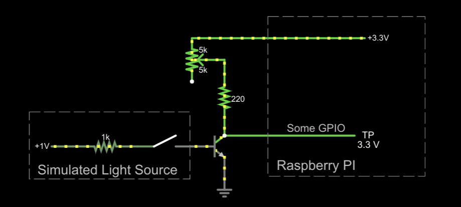
Here is a basic phototransistor circuit that would be combined with one of the circuits above (since you still want the ability to trigger the buttons):
The potentiometer is used to change the sensitivity of the circuit. Again, this is just a starting point to give you some terms to search for. Building up the circuit above (or an alternate example you find) and testing it on a breadboard is recommended before building anying permanent.
If you go with a photodiode, the circuit will be a bit different. I also found some photodiode modules on Amazon that look easy to use. Another option to consider.
| Qty | Value | Footprint | References |
|---|---|---|---|
| 4 | 220 | Resistor_THT:R_Axial_DIN0207_L6.3mm_D2.5mm_P10.16mm_Horizontal | R5, R6, R7, R8 |
| 2 | 100k | Resistor_THT:R_Axial_DIN0207_L6.3mm_D2.5mm_P10.16mm_Horizontal | R1, R2 |
| 2 | 1k | Resistor_THT:R_Axial_DIN0207_L6.3mm_D2.5mm_P10.16mm_Horizontal | R3, R4 |
| 2 | BS170 | Package_TO_SOT_THT:TO-92_Inline_Wide | Q1, Q2 |
| 1 | BUTTON_PINS | Connector_PinSocket_2.54mm:PinSocket_1x02_P2.54mm_Vertical | J2 |
| 1 | PI Connector | Connector_PinSocket_2.54mm:PinSocket_2x20_P2.54mm_Vertical | J1 |
| 1 | WIRELESS_GND | Connector_PinSocket_2.54mm:PinSocket_1x01_P2.54mm_Vertical | J3 |


pablozg/freeds
Derivador de energía solar excedente creado por Pablo Zerón, Diseño PCB por Amcalo, Tester original por Aeizoon, Wiki por Zoilo Mora

PhysicsDptAngers/polyUAnalog
Open source, analog and polyphonic synthesizer


DRWJSCHMIDT/T41
This is the repository for the officially released V10, V11, and V12 versions of the T41 Software Defined Transceiver hardware and kits.

sffubs/dactyl_manuform_gimbal
Instrutions and designs for building the dactyl-manuform-gimbal keyboard
It measures 58.4 × 27.3 mm and has 2 copper layers, 1.6 mm thick.
13 parts, built around the BS170. The full list of its parts is on this page, with links to each part's symbol and footprint where PCBKit's library has them.
From the mattwach/game_controller_latency_tester repository on GitHub, at the commit this page was made from: the board is latency_schematic/latency_schematic.kicad_pcb and its schematic latency_schematic/latency_schematic.kicad_sch. PCBKit opens the board in the browser, with nothing to install.
Its repository states no licence, so its author keeps all rights: ask mattwach before reusing the design.