4 layers65 × 30 mm
Icepi zero
hackclub/OnBoard
💡 Join 1,000 teenagers and make your first PCB with a $100 grant!
122 parts915

 matterwaves/analog-lockbox-v2
Analog lockbox v2 is an open-source printed circuit board by matterwaves, from the matterwaves/analog-lockbox-v2 repository on GitHub. It is a 4-layer board of 100 × 100 mm with 122 parts on 63 nets, routed with 373 tracks and 55 vias.
Its parts include 42 resistors, 27 capacitors, 9 connectors, 7 ICs and 5 switches.
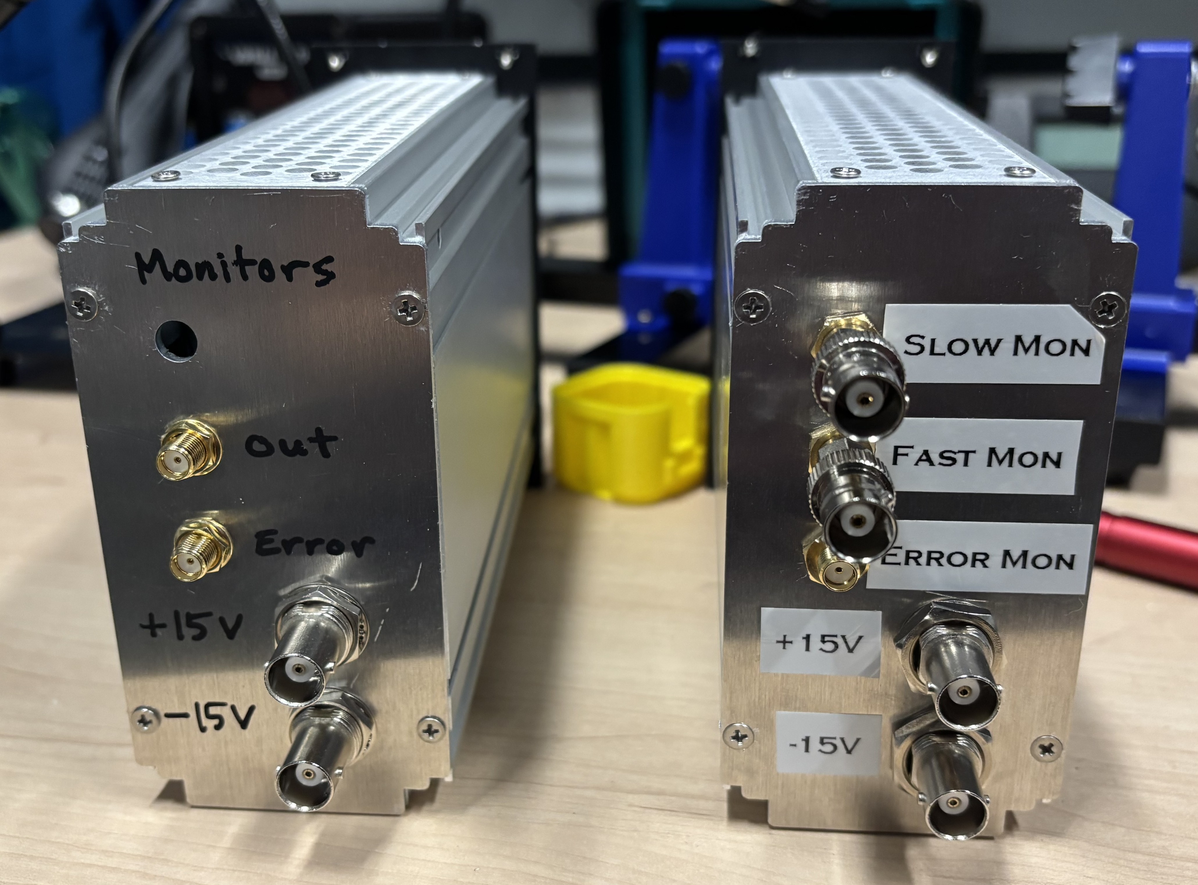
This repository contains the design files for the analog lockboxes used in the B219 Cs cavity atom interferometer experiment. Like most of our PCBs, it is designed to be powered via JST connector from a dedicated regulated DC power supply board. The board, with mostly edge facing SMAs and POTs, has a narrow profile for space-efficient mounting in a 3U 19" subrack. Our front panels have outer holes to mount within a 3U subrack and inner holes for both the 12HP Vector Electronics EMB subrack modules and the 104x55 mm Hammond 1457 series enclosures.
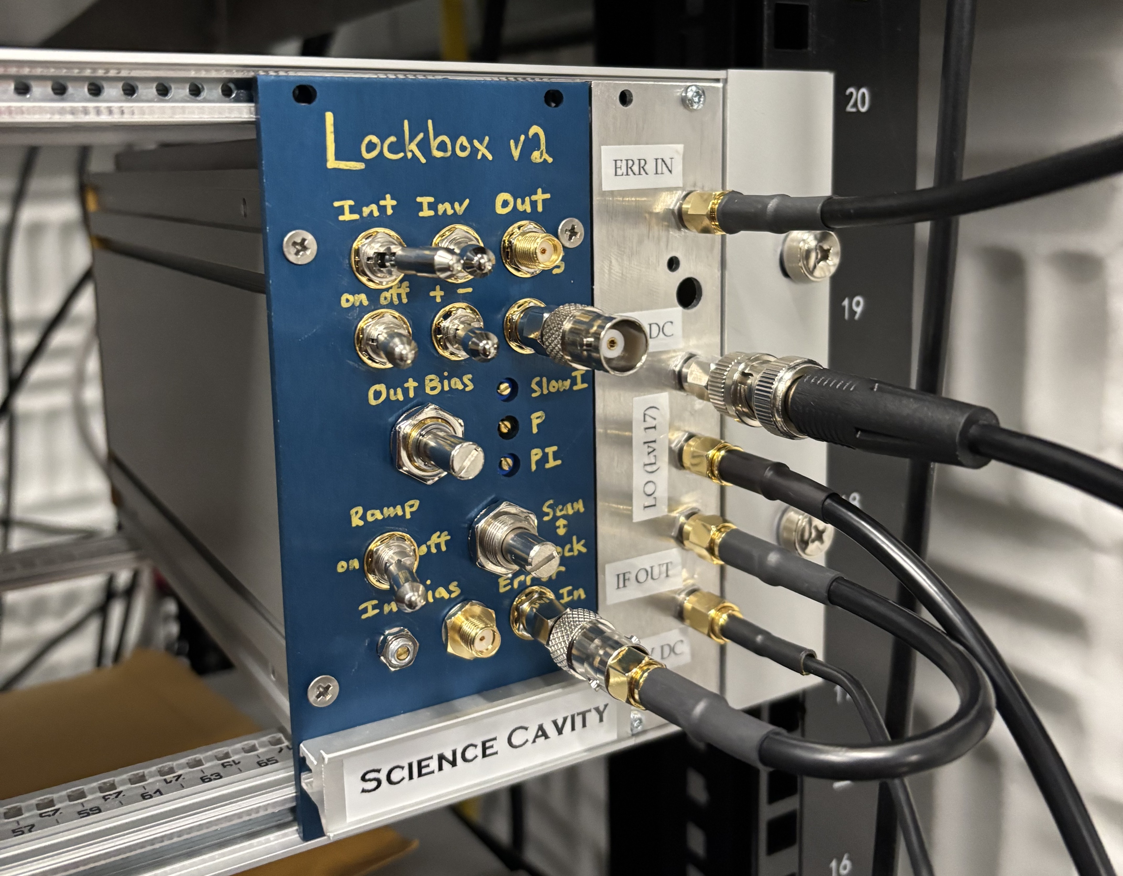
The circuit design, pictured below, is based on the so-called "Holger's World Famous Lockbox" commonly used in the Müller group.
It is essentially just an analog PI loop with the addition of a Schmitt trigger looped in with the integrator in order to internally produce a triangle wave.
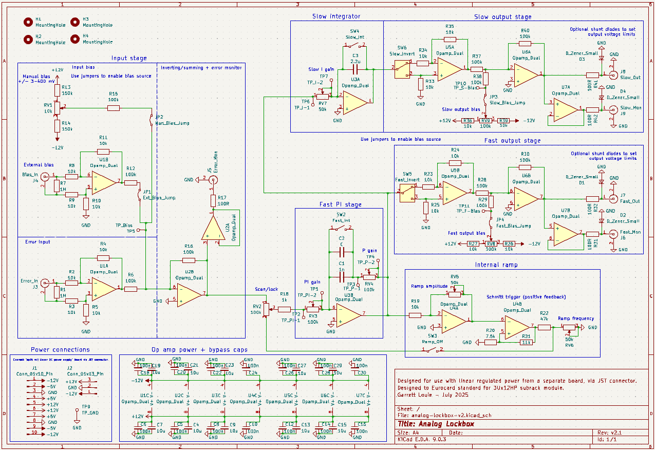 N.B. The schematic shows very high resistor and potentiometer values. Do not use these high values if you want MHz bandwidth. Use only 1kR-10kR in the fast loop.
One can add an optional external error bias (via SMA) and/or manual error bias (via trimpot) enabled by jumpers. The output bias for the fast and slow locks are also enabled by jumpers; usually just one output bias is needed, unless, e.g., you want to bias a piezo to a certain voltage using the slow lock. The internal triangle wave ramp has a variable amplitude and frequency whic is set by two trimpots RV5 (changes amplitude and frequency) and RV6 (changes frequency). Note that the I gain also affects the frequency of the ramp. Both the fast and slow outputs have optional shunt diodes for setting voltage limits. Most of the op amp rails have dual bypass caps--a ceramic cap at 100 nF, and a electrolytic cap at 10 μF (more lossy than ceramic to damp parasitic LC resonances between the caps)--though it is not neccessary to place the larger electrolytic caps at every op amp.
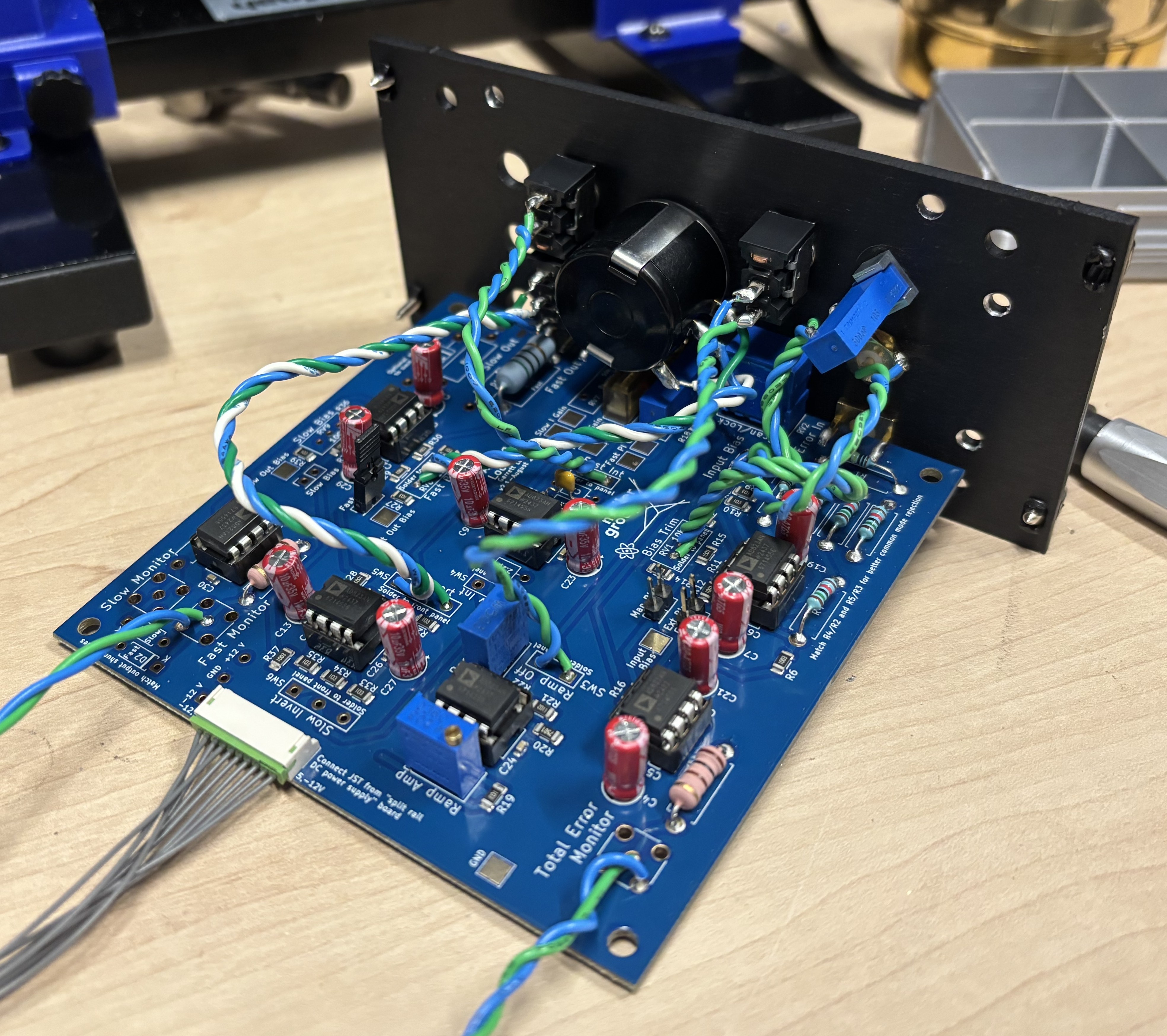
If using an anodized/powder coated front panel (which looks a lot sexier than plain aluminum), one should countersink the mounting holes to ensure grounding to the main chassis.
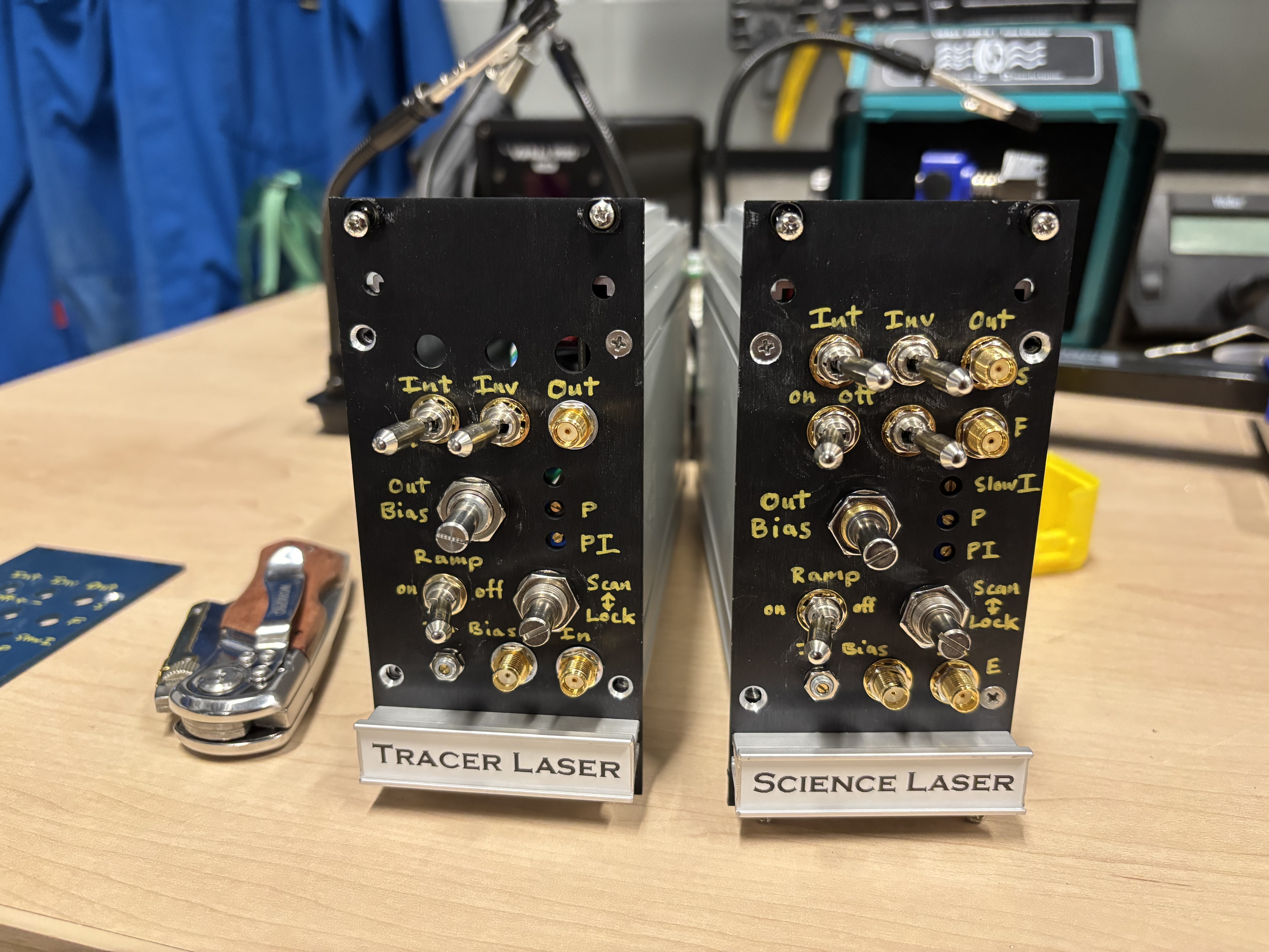
The back panel is left unanodized for better grounding (since aesthetics don't matter as much).
| Qty | Value | Footprint | References |
|---|---|---|---|
| 15 | 10k | Resistor_SMD:R_1206_3216Metric | R8, R9, R10, R11, R19, R23, R24, R25, R26, R27, R33, R34, R35, R36, R39 |
| 14 | 100n | Capacitor_SMD:C_0603_1608Metric | C5, C6, C8, C10, C12, C14, C16, C18, C20, C22, C24, C26, C28, C30 |
| 10 | 100k | Resistor_SMD:R_1206_3216Metric | R6, R12, R15, R16, R28, R29, R30, R37, R38, R40 |
| 10 | 10u | Capacitor_THT:CP_Radial_D5.0mm_P2.00mm | C4, C7, C9, C13, C15, C19, C21, C23, C27, C29 |
| 7 | Opamp_Dual | Package_DIP:DIP-8_W7.62mm | U1, U2, U3, U4, U5, U6, U7 |
| 4 | 10k | Resistor_THT:R_Axial_DIN0411_L9.9mm_D3.6mm_P12.70mm_Horizontal | R2, R3, R4, R5 |
| 4 | MountingHole | MountingHole:MountingHole_3.2mm_M3 | H1, H2, H3, H4 |
| 3 | 100R | Resistor_THT:R_Axial_DIN0411_L9.9mm_D3.6mm_P12.70mm_Horizontal | R17, R31, R42 |
| 2 | 100R | Resistor_THT:R_Axial_DIN0414_L11.9mm_D4.5mm_P15.24mm_Horizontal | R32, R41 |
| 2 | 100k | Potentiometer_THT:Potentiometer_Bourns_3296W_Vertical | RV8, RV9 |
| 2 | 100k | Potentiometer_THT:Potentiometer_Bourns_3006P_Horizontal | RV3, RV4 |
| 2 | 150k | Resistor_SMD:R_1206_3216Metric | R13, R14 |
| 2 | 1M | Resistor_THT:R_Axial_DIN0411_L9.9mm_D3.6mm_P12.70mm_Horizontal | R1, R7 |
| 2 | 50k | Potentiometer_THT:Potentiometer_Bourns_3296W_Vertical | RV5, RV6 |
| 2 | D_Zener_Small | Diode_THT:D_A-405_P7.62mm_Horizontal | D2, D4 |
| 2 | D_Zener_Small | Diode_THT:D_DO-15_P15.24mm_Horizontal | D1, D3 |
| 1 | 100k | SamacSys_Parts:51CADE24E20L | RV2 |
| 1 | 10k | Potentiometer_THT:Potentiometer_Bourns_3296W_Vertical | RV1 |
| 1 | 11k | Resistor_SMD:R_1206_3216Metric | R21 |
| 1 | 1k | Resistor_SMD:R_1210_3225Metric | R18 |
| 1 | 1n | Capacitor_THT:C_Axial_L3.8mm_D2.6mm_P7.50mm_Horizontal | C1 |
| 1 | 2.2u | Capacitor_THT:C_Axial_L3.8mm_D2.6mm_P7.50mm_Horizontal | C3 |
| 1 | 47k | Resistor_SMD:R_1206_3216Metric | R22 |
| 1 | 50k | Potentiometer_THT:Potentiometer_Bourns_3006P_Horizontal | RV7 |
| 1 | 7.5k | Resistor_SMD:R_1206_3216Metric | R20 |
| 1 | Bias_In | Connector_Coaxial:SMA_Amphenol_132134_Vertical | J4 |
| 1 | C | Capacitor_THT:C_Axial_L3.8mm_D2.6mm_P7.50mm_Horizontal | C2 |
| 1 | Conn_01x03_Pin | Connector_Wire:SolderWire-0.25sqmm_1x03_P4.2mm_D0.65mm_OD1.7mm | J2 |
| 1 | Conn_01x10_Pin | Connector_JST:JST_ZH_B10B-ZR_1x10_P1.50mm_Vertical | J1 |
| 1 | Error_In | Connector_Coaxial:SMA_Amphenol_132289_EdgeMount | J3 |
| 1 | Error_Mon | Connector_Coaxial:SMA_Amphenol_132134_Vertical | J5 |
| 1 | Ext_Bias_Jump | Connector_PinHeader_2.54mm:PinHeader_2x01_P2.54mm_Vertical | JP1 |
| 1 | Fast_Bias_Jump | Connector_PinHeader_2.54mm:PinHeader_2x01_P2.54mm_Vertical | JP4 |
| 1 | Fast_Int | Connector_Wire:SolderWire-0.25sqmm_1x02_P4.5mm_D0.65mm_OD2mm | SW2 |
| 1 | Fast_Invert | Connector_Wire:SolderWire-0.25sqmm_1x03_P4.5mm_D0.65mm_OD2mm | SW5 |
| 1 | Fast_Mon | Connector_Coaxial:SMA_Amphenol_132134_Vertical | J6 |
| 1 | Fast_Out | Connector_Coaxial:SMA_Amphenol_132289_EdgeMount | J7 |
| 1 | LOGO | LOGO | G*** |
| 1 | Man_Bias_Jump | Connector_PinHeader_2.54mm:PinHeader_2x01_P2.54mm_Vertical | JP2 |
| 1 | Ramp_Off | Connector_Wire:SolderWire-0.25sqmm_1x02_P4.5mm_D0.65mm_OD2mm | SW3 |
| 1 | Slow_Bias_Jump | Connector_PinHeader_2.54mm:PinHeader_2x01_P2.54mm_Vertical | JP3 |
| 1 | Slow_Int | Connector_Wire:SolderWire-0.25sqmm_1x02_P4.5mm_D0.65mm_OD2mm | SW4 |
| 1 | Slow_Invert | Connector_Wire:SolderWire-0.25sqmm_1x03_P4.5mm_D0.65mm_OD2mm | SW6 |
| 1 | Slow_Mon | Connector_Coaxial:SMA_Amphenol_132134_Vertical | J9 |
| 1 | Slow_Out | Connector_Coaxial:SMA_Amphenol_132289_EdgeMount | J8 |
| 1 | TP_Bias | TestPoint:TestPoint_Pad_3.0x3.0mm | TP5 |
| 1 | TP_F-Bias | TestPoint:TestPoint_Pad_3.0x3.0mm | TP11 |
| 1 | TP_GND | TestPoint:TestPoint_Pad_3.0x3.0mm | TP9 |
| 1 | TP_I-1 | TestPoint:TestPoint_Pad_3.0x3.0mm | TP6 |
| 1 | TP_I-2 | TestPoint:TestPoint_Pad_3.0x3.0mm | TP7 |
| 1 | TP_P-1 | TestPoint:TestPoint_Pad_3.0x3.0mm | TP3 |
| 1 | TP_P-2 | TestPoint:TestPoint_Pad_3.0x3.0mm | TP4 |
| 1 | TP_PI-1 | TestPoint:TestPoint_Pad_3.0x3.0mm | TP2 |
| 1 | TP_PI-2 | TestPoint:TestPoint_Pad_3.0x3.0mm | TP1 |
| 1 | TP_S-Bias | TestPoint:TestPoint_Pad_3.0x3.0mm | TP10 |
It measures 100 × 100 mm and has 4 copper layers, 1.6 mm thick.
122 parts. The full list of its parts is on this page, with links to each part's symbol and footprint where PCBKit's library has them.
From the matterwaves/analog-lockbox-v2 repository on GitHub, at the commit this page was made from: the board is analog-lockbox-v2/analog-lockbox-v2.kicad_pcb and its schematic analog-lockbox-v2/analog-lockbox-v2.kicad_sch. PCBKit opens the board in the browser, with nothing to install.
Its repository states no licence, so its author keeps all rights: ask matterwaves before reusing the design.
hackclub/OnBoard
💡 Join 1,000 teenagers and make your first PCB with a $100 grant!

anthony-bernaert/ftdi-jtag-programmer
FTDI-based JTAG Programmer Circuit for FPGAs

introlab/t-top
T-Top is a tabletop robot designed with advanced audio and vision sensors, deep learning perceptual processing and telecommunication capabilities to provide richer interaction modalities and develop higher cognitive…


pollen-robotics/elec_grabette
Set of electronic boards for Grabette/Gripette

tomwimmenhove/MoonPi
Allwinner V3S board with mini PCIe slot for 4G LTE module


schilkp/PmodADC
A fully discrete 14bit, 41kHz, FPGA-controlled Successive-Approximation Audio ADC and R2R Audio DAC.