2 layers126.8 × 48.3 mm
Dc25badge
Matir/DC25Badge
This is an unofficial badge I made for DEF CON 25. It's a blinding party-style badge with 48 individually addressable RGB LEDs.
101 parts1Apache-2.0

 Matir/DC25Badge1
This is an unofficial badge I made for DEF CON 25. It's a blinding party-style badge with 48 individually addressable RGB LEDs.
Protospin is an open-source printed circuit board by Matir, from the Matir/DC25Badge repository on GitHub, published under the Apache-2.0 licence. It is a 2-layer board of 57.3 × 38.1 mm with 32 parts on 52 nets, routed with 382 tracks and 50 vias.
It is built around the ATSAMD21E18A-AU, 74AHCT125D and TPS61232DRC, with the MIC5305YML among its other parts. Its parts include 15 capacitors, 6 ICs, 4 resistors, 4 connectors and 1 switch. It belongs with the SAM D and SAM boards of this library.


This is an unofficial badge I made for DEF CON 25. It's a blinding party-style badge with 48 individually addressable RGB LEDs. Off an adequate battery (a medium LiPo) you can run all lights at max brightness, but that is bright.
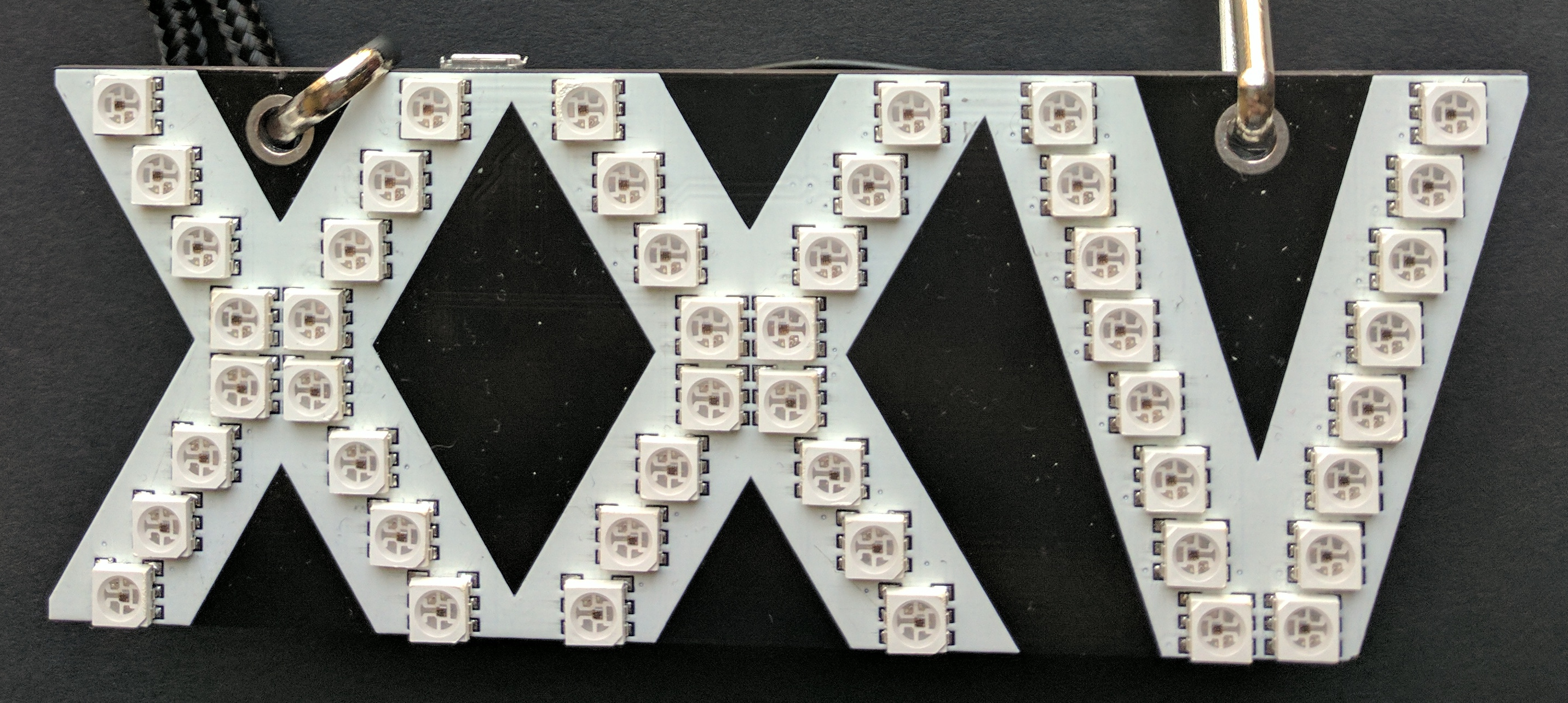
This is intended as a one-time release for others to learn from and/or remix the firmware. I don't plan to take pull requests since it will be over and I'll be on to another project by the release. :)
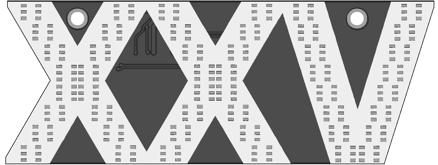
The PCB was designed using Kicad. Source files are in the dc25badge/
directory.
To build the firmware, you'll need 3 things: this git repository, the Atmel
Software Framework (ASF), and an ARM compiler. On Debian & Ubuntu, you'll want
to install the packages gcc-arm-none-eabi and binutils-arm-none-eabi.
setup.sh in the src/ directory will get you the latest build of the ASF (at
least, it worked when this was prepared). Running make will build the
firmware image.
To choose which patterns are available by pushing the mode button, edit the
array in pattern.c.
To upload a firmware image, you'll need to get into the bootloader. To do this, "double tap" the reset button, and the reset LED will stay solid green. (If it doesn't, you're not in the bootloader.)
You can then use bossa or just run make upload from the src/ directory to
upload the current firmware build.
This is not an official Google product.
| Qty | Value | Footprint | References |
|---|---|---|---|
| 6 | 0.1u | Capacitors_SMD:C_0805_HandSoldering | C2, C3, C4, C9, C10, C11 |
| 4 | 22u | Capacitors_SMD:C_0805_HandSoldering | C8, C13, C14, C15 |
| 3 | 10k | Resistors_SMD:R_0805_HandSoldering | R2, R3, R4 |
| 2 | 1u | Capacitors_SMD:C_0805_HandSoldering | C1, C6 |
| 2 | 22pF | Capacitors_SMD:C_0805_HandSoldering | C5, C7 |
| 2 | APA102 | Badge_Parts:APA102 | U5, U6 |
| 1 | 10u | Capacitors_SMD:C_0805_HandSoldering | C12 |
| 1 | 32.768k | Crystals:Crystal_SMD_G8 | Y1 |
| 1 | 330 | Resistors_SMD:R_0805_HandSoldering | R1 |
| 1 | 74AHCT125 | SMD_Packages:SOIC-14_N | U4 |
| 1 | ATSAMD21E18A-AU | Housings_QFP:TQFP-32_7x7mm_Pitch0.8mm | U2 |
| 1 | BATT | Connectors_JST:JST_PH_S2B-PH-SM4-TB_02x2.00mm_Angled | P1 |
| 1 | CONN_01X16 | Pin_Headers2:Pin_Header_Straight_1x16_Pitch2.54mm_SMD_Pin1Right | P4 |
| 1 | CONN_CORTEX | Pin_Headers2:Pin_Header_Straight_2x05_Pitch1.27mm_SMD | P3 |
| 1 | L_Core_Ferrite | Badge_Parts:Inductor_6.5x6 | L1 |
| 1 | MIC5305 | TO_SOT_Packages_SMD:SOT-23-5 | U1 |
| 1 | RESET | Buttons_Switches_SMD:SW_SPST_EVQP0 | SW1 |
| 1 | TPS61232 | Badge_Parts:PSON-10P | U3 |
| 1 | USB_OTG | Badge_Parts:Amphenol_10118192 | P2 |
Matir/DC25Badge
This is an unofficial badge I made for DEF CON 25. It's a blinding party-style badge with 48 individually addressable RGB LEDs.

wattnotions/povbot2
Look in 3dprint folder to find a 3mf file with the chassis , camera holder and wheels ready to print.


google/myelin-acorn-electron-hardware
Phillip Pearson's retro hardware projects for the Acorn Electron

polesskiy-dev/iot-risk-data-logger-nfc-samd21-hardware
Hardware (schematics, PCB, BOM) for iot-risk-data-logger-nfc-samd21 project


myelin/arcflash
Adapter board to allow an "arcflash" A3000 ROM emulator to work on a Risc PC.
It measures 57.3 × 38.1 mm and has 2 copper layers, 1.6 mm thick.
32 parts, built around the ATSAMD21E18A-AU, 74AHCT125D, TPS61232DRC and MIC5305YML. The full list of its parts is on this page, with links to each part's symbol and footprint where PCBKit's library has them.
From the Matir/DC25Badge repository on GitHub, at the commit this page was made from: the board is protospin/protospin.kicad_pcb. PCBKit opens the board in the browser, with nothing to install.
Its repository publishes it under the Apache-2.0 licence: you may reuse it on that licence's terms (keep the author's notice, and for a copyleft licence share your changes alike).