
2 layers103.8 × 50 mm
Galagino pcb set
harbaum/galagino
A Galaga, Pac-Man and Donkey Kong arcade emulator for the ESP32
26 parts558

 mathiasvan/LevelmetingWaterputV4
ESP32-based water well level monitoring using a QDY30A RS485 sensor. Reads water level, uploads data to ThingSpeak, and supports remote logging and commands via Telnet (PuTTY). Includes wiring diagrams, setup instructions, and example telnet commands for easy integration and troubleshooting.
Waterputv4Schematics is an open-source printed circuit board by mathiasvan, from the mathiasvan/LevelmetingWaterputV4 repository on GitHub, published under the GPL-3.0 licence. It is a 2-layer board with 4 parts on 42 nets.
It is built around the ESP32-DEVKITC-VE. Its parts include 2 ICs and 2 connectors. It belongs with the interfaces and adapters and sensors and measurement boards and the ESP32 boards of this library.
This project is V4 in the levelmeting waterput project. It uses the QDY30A level sensor with RS485 protocol because all the previous sensors broke.
This project uses the ModbusMaster library which can be installed from the Library Manager in the Arduino IDE.
Thanks lejmr for this diagram. I used it to test my sensor. It is wrong for the TX and RX pins, they should be swapped. (See below for more.) The rest is the same as in this diagram.
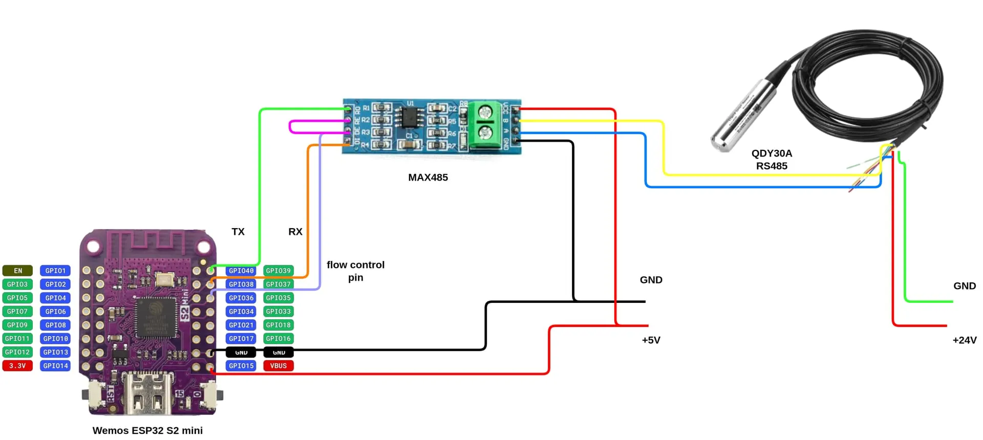
My adaptation: I used pin 2 on the ESP32 to connect the DE and RE pins from the MAX485 module.
See the final KiCad diagram under the waterputv4Schematics folder. Here is a screenshot in case you don't have KiCad.
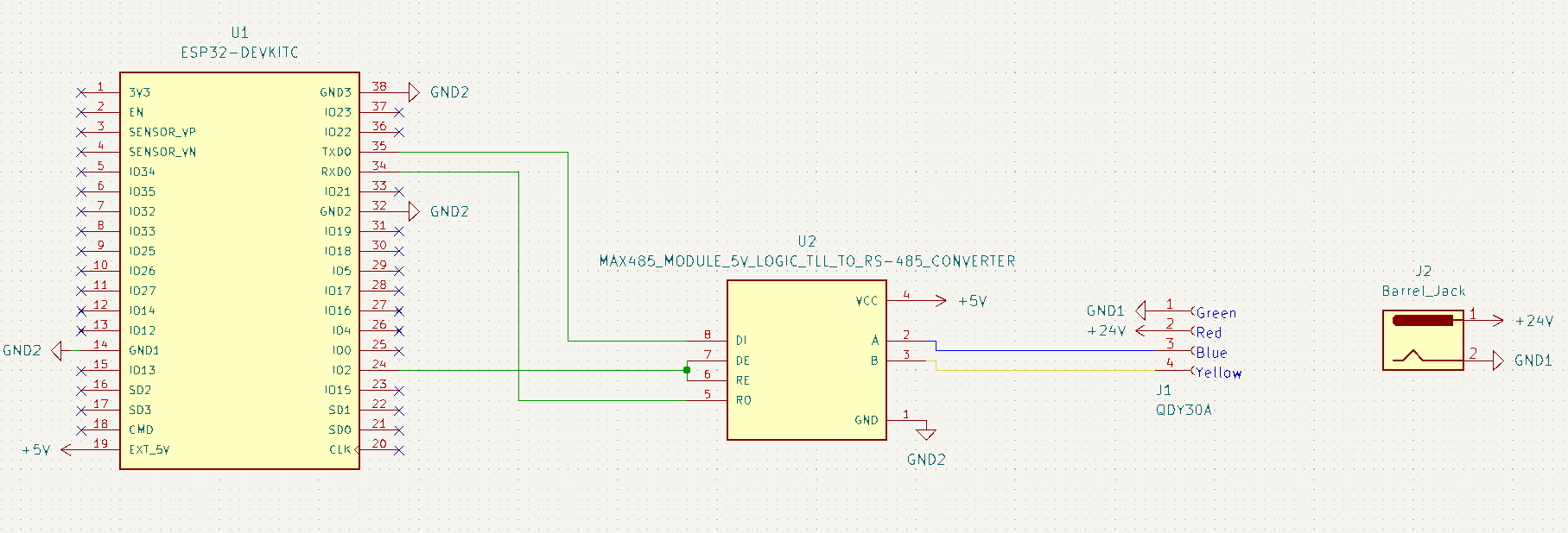
This took a lot of trial and error but I got it working in the end. Some important remarks:
testcode.credentials.h file in the same folder as the final code. You need to fill this template with your own credentials.#define mySSID "xxxxx"
#define myPASSWORD "xxxxx"
#define myChannelNumber 111111
#define myWriteAPIKey "xxxxxx"After connecting to your ESP32 using PuTTY (see IP address in Serial Monitor), you can use the following commands in the telnet console:
ping
The ESP32 will respond with pong, show the current sensor height, and display the time remaining until the next automatic data upload to ThingSpeak.
send data
Immediately triggers a sensor reading and uploads the value to ThingSpeak, regardless of the regular upload interval.
Example session:
> ping
pong
Doing a height reading...
Data at adress 4: 158
Converted height: 15.8cm
15.80
Time to next data send: 122 seconds

> send data
Sending data now...
Data at adress 4: 158
Converted height: 15.8cm
Height: 15.8cm
Uploading data to ThingSpeak...
Successful upload to ThingSpeak.
Height: 15.80 uploaded to ThingSpeak server.
If you enter an unknown command, nothing will happen. Commands are case-sensitive.
Tip:
Make sure you have connected to the correct IP address and that your ESP32 is powered and connected to WiFi.
reconnect wifi command.| Qty | Value | Footprint | References |
|---|---|---|---|
| 1 | Barrel_Jack | Connector_BarrelJack:BarrelJack_Horizontal | J2 |
| 1 | ESP32-DEVKITC | ESP32-DEVKITC:MODULE_ESP32-DEVKITC | U1 |
| 1 | MAX485_MODULE_5V_LOGIC_TLL_TO_RS-485_CONVERTER | MAX485_MODULE_5V_LOGIC_TLL_TO_RS-485_CONVERTER:MODULE_MAX485_MODULE_5V_LOGIC_TLL_TO_RS-485_CONVERTER | U2 |
| 1 | QDY30A | Connector_JST:JST_XH_B4B-XH-AM_1x04_P2.50mm_Vertical | J1 |
harbaum/galagino
A Galaga, Pac-Man and Donkey Kong arcade emulator for the ESP32

RParkerE/OpenSilicon
OpenSilicon enables DIY semiconductor fabrication with open-source guides for building IC equipment at home. The project includes BOMs, 3D files, firmware, and PDKs, supporting makers and researchers in chip fabrication.

cole8888/SRNE-Solar-Charge-Controller-Monitor
Read data from SRNE solar charge controllers.


ste2425/PSP-Bluetooth-AVConnector
An AV-Out Breakout library for the PSP. Providing Kicad symbols and footprints to interface with the PSP 2/3K AVOut socket (also known as the TVOut socket)

4 parts, built around the ESP32-DEVKITC-VE. The full list of its parts is on this page, with links to each part's symbol and footprint where PCBKit's library has them.
From the mathiasvan/LevelmetingWaterputV4 repository on GitHub, at the commit this page was made from: the board is waterputv4Schematics/waterputv4Schematics.kicad_pcb and its schematic waterputv4Schematics/waterputv4Schematics.kicad_sch. PCBKit opens the board in the browser, with nothing to install.
Its repository publishes it under the GPL-3.0 licence: you may reuse it on that licence's terms (keep the author's notice, and for a copyleft licence share your changes alike).