
2 layers
ESP32Anglerfish
Matchboxscope/Matchboxscope
ESP32-based mini microscope for fluidic device observation
7 parts103
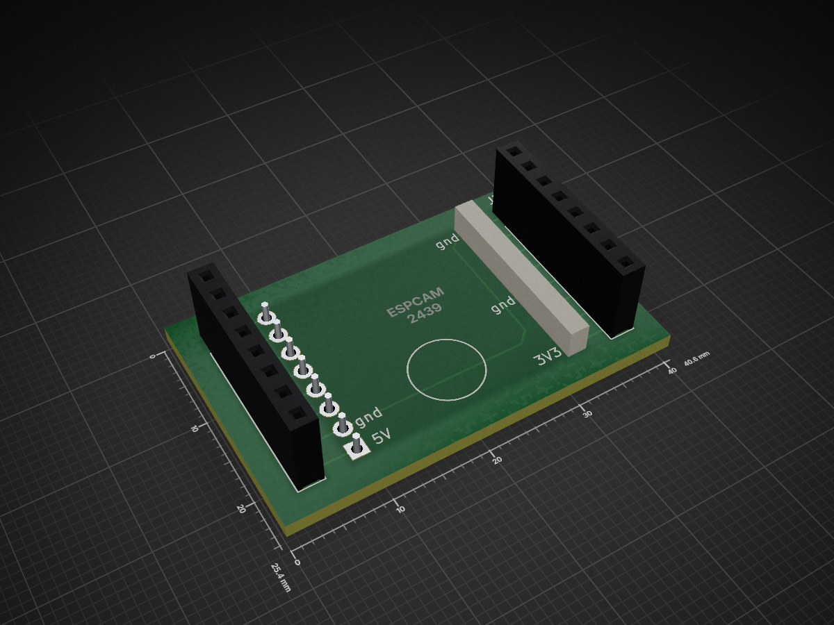
ESP32-based mini microscope for fluidic device observation
Espcam is an open-source printed circuit board by Matchboxscope, from the Matchboxscope/Matchboxscope repository on GitHub. It is a 2-layer board of 40.6 × 25.4 mm with 3 parts on 14 nets, routed with 23 tracks and 0 vias.
Its parts include 2 connectors and 1 IC.
This is a repository for the smallest standalone low-cost open-source DIY incubator-contained microscope that can be used for a gazillion different applications. Sounds interesting? Continue reading!
The core component of this device is a ESP32 microcontroller that is packed with a small Camera (OV2460) and microSD card slot, which makes it a perfect match for your microscopy project. In the most minimal version, you don't need anything but the ESP32-CAM and perhaps some chewing gum to raise the objective lens in order to create a finite corrected microscope.
However, we wanted to make the microscope a bit more practical and created some 3D printed parts that will realize the following devices:
The Anglerfish: This device is well preserved in your beloved jars and hence watertight. Why? Throw it in your nearby pond and collect data how microfilm grows on the jars' surface. Fun! Follow the BLUE PILL 🔵
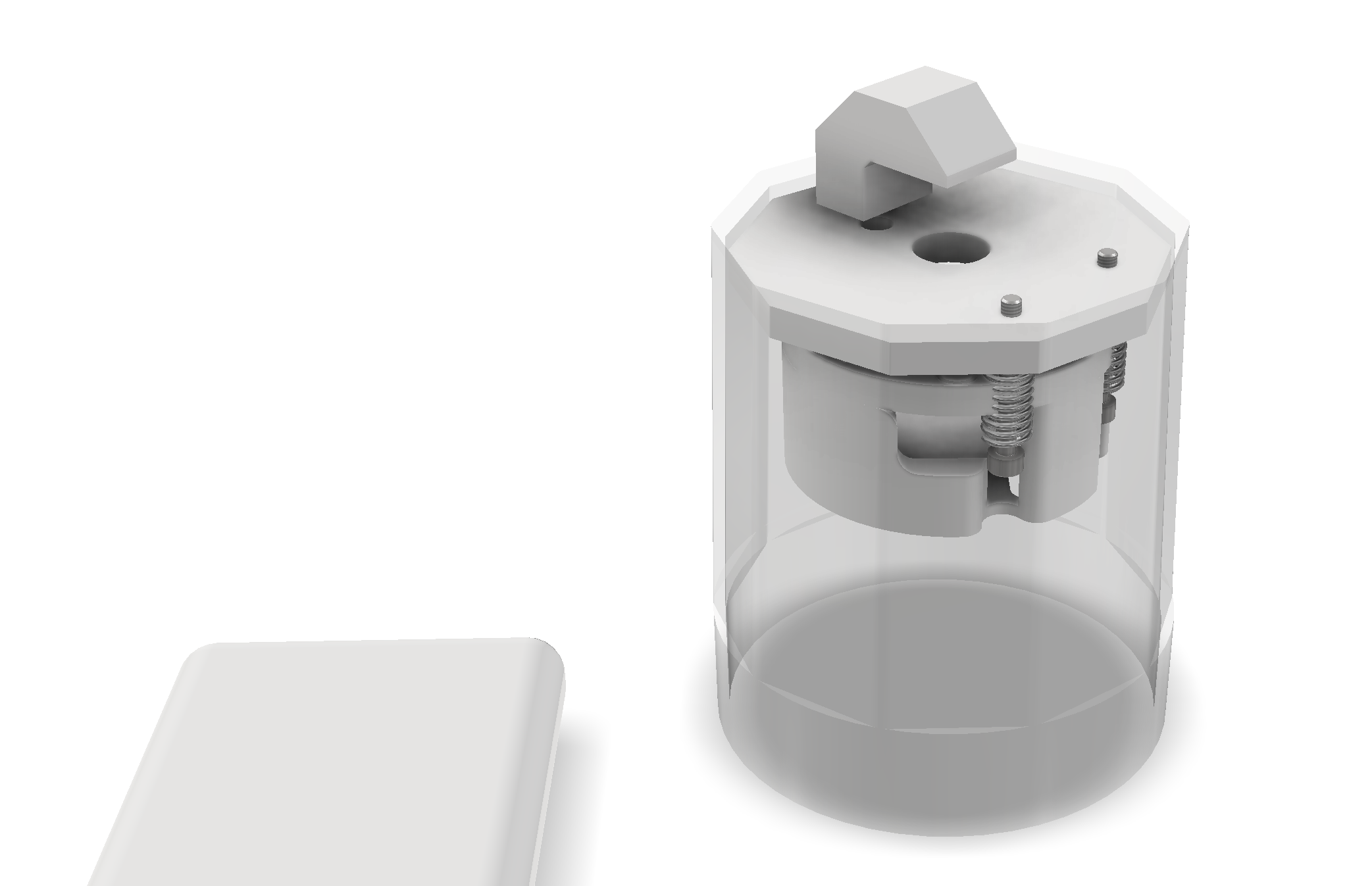
The Matchboxscope: This is a simple self-contained microscope, e.g. for tacking snapshots of your microfluidic chips, your parasite containing slides or just for fun. It comes with a minimum number of parts, but offers a spring-loaded z-stage. Also ideal for your incubator-contained microscopy experiments! Follow the RED PILL 🔴
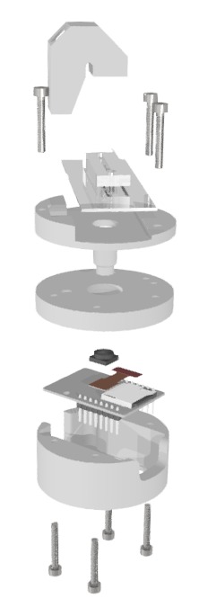
The Z-Stacker: It adds an automatic focusing unit to the Matchboxscope in order to create temporal Z-stacks of your beloved cell cultures. It needs more electronics, but still relies on the ESP32-CAM only. Lots of fun, too. Follow the GREEN PILL 🟢
Still curious? Continue Reading by clicking on individual device sub-pages!
In order to get the code compiled and uploaded to your ESP32 camera board, a number of steps have to be carried out to prepare the system.
This code is written for the AI_THINKER
https://raw.githubusercontent.com/espressif/arduino-esp32/gh-pages/package_esp32_dev_index.json
When installing the board, go for the version 2.0.3.ino and flash the project (v0.1)Toolsselect your board (DEV Module), port and enable the PSRAM enable 4MB external PSRAM.ATTENTION for Android users: The Wi-Fi in access point mode (AP) does not offer internet, hence Android uses available cellular/mobile data and won't open the local address (192.168.4.1). Solution: Switch off mobile data or disable Wifi+
Wi-Fi settings:
Please have a look in the Wi-Fi settings to adjust them according to your network configuration:
`cpp boolean hostWifiAP = true; // set this variable if you want the ESP32 to be the host const char* mSSID = "Blynk"; const char* mPASSWORD = "12345678"; const char* mSSIDAP = "Matchboxscope"; ``
For the HTML and CSS files, you can upload the files to
Getting many images in an autonomous "diving" experiment is key. For this, we wrote a firmware that enables you to find the focus and as soon as you're done, the microcontroller goes into deep-sleep mode to save energy. The following steps are important to carry out before your experiment.
The protocol
X minutes to take a photo and save it on the SD card.In the deep-sleep setting, it consumes virtually no power.
Problem/thoughts:
setup())That's the software for the Matchboxscope:

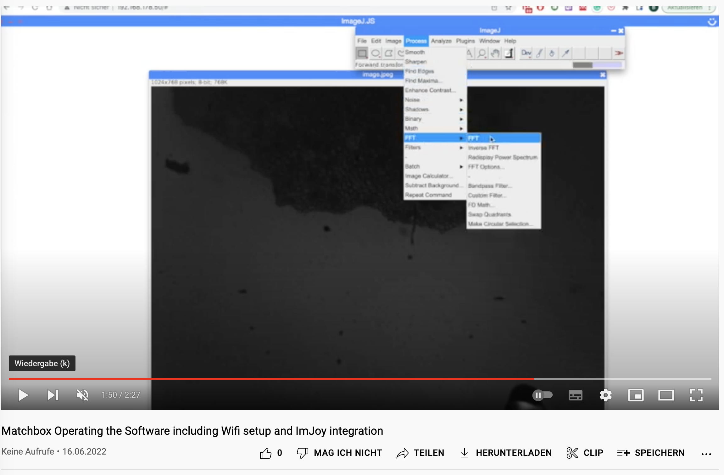
And a more in-detail tutorial on how to use the software:
This project is open so that anyone can get involved. You don't even have to learn CAD designing or programming. Find ways you can contribute in CONTRIBUTING
This project is open-source and is released under the CERN open hardware license. Our aim is to make the kits commercially available. We encourage everyone who is using our Toolbox to share their results and ideas, so that the Toolbox keeps improving. It should serve as an easy-to-use and easy-to-access general purpose building block solution for the area of STEAM education. All the design files are generally for free, but we would like to hear from you how is it going.
You're free to fork the project and enhance it. If you have any suggestions to improve it or add any additional functions, make a pull-request or file an issue.
Please find the type of licenses here
REMARK: All files have been designed using Autodesk Inventor 2019 (EDUCATION)
If you find this project useful, please like this repository, follow us on Twitter and cite the webpage! :-)
| Qty | Value | Footprint | References |
|---|---|---|---|
| 1 | Conn1 | Connector_PinSocket_2.54mm:PinSocket_1x08_P2.54mm_Vertical | J1 |
| 1 | Conn2 | Connector_PinSocket_2.54mm:PinSocket_1x08_P2.54mm_Vertical | J2 |
| 1 | ESPCAM | espcam:ESPCAM_bottom | U1 |
It measures 40.6 × 25.4 mm and has 2 copper layers, 1.6 mm thick.
3 parts. The full list of its parts is on this page, with links to each part's symbol and footprint where PCBKit's library has them.
From the Matchboxscope/Matchboxscope repository on GitHub, at the commit this page was made from: the board is KiCAD/ESP32Anglerfish/libraries/espcam.kicad_pcb and its schematic KiCAD/ESP32Anglerfish/ESP32Anglerfish.kicad_sch. PCBKit opens the board in the browser, with nothing to install.
Its repository states no licence, so its author keeps all rights: ask Matchboxscope before reusing the design.
Matchboxscope/Matchboxscope
ESP32-based mini microscope for fluidic device observation


hzeller/rpi-rgb-led-matrix
Controlling up to three chains of 64x64, 32x32, 16x32 or similar RGB LED displays using Raspberry Pi GPIO


atopile/atopile
Design circuit boards with code! ✨ Get software-like design reuse 🚀, validation, version control and collaboration in hardware; starting with electronics ⚡️


hackclub/sprig
🍃 Learn to code by making games in a JavaScript web-based game editor.