2 layers148.6 × 192.2 mm
Badge
NuttyShell/NuttyBadge
NuttyBadge: A NuttyShell crafted multi-tool. Opensourced Hardawre and Software
169 parts31GPL-3.0

 masaccio/picow_day_clock
A Raspberry Pi Pico clock that shows the time and day of week using a Waveshare ST7789V3 LCD Module
Pico dow clock is an open-source printed circuit board by masaccio, from the masaccio/picow_day_clock repository on GitHub, published under the MIT licence. It is a 2-layer board with 4 parts on 60 nets.
It is built around the AMS1117-3.3 and AO3400A. Its parts include 1 IC and 1 transistor. It belongs with the lEDs and displays boards and the RP2040 boards of this library.


This project is a work in progress.
The clock is now feature complete from a software perspective though if this were scaled up for sale, it would need user-level configuration using a Wi-Fi connection and a web-server to provide the credentials and would also need some means of initiating a factory reset. Better still would be bluetooth discovery from a phone app to configure the clock for things like timezones, colors and fonts as well as the Wi-Fi credentials. The clock build looks like this:
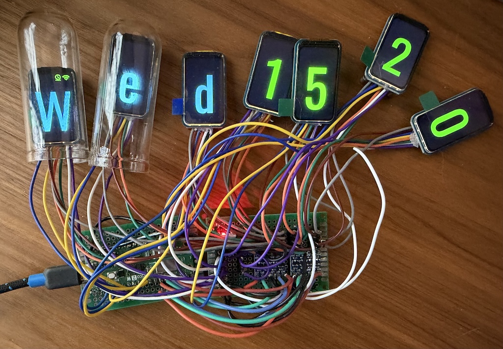
Next steps in the project are:
This project is the software, hardware design and clock enclosure design for an LCD clock driven by the Raspberry Pi Pico 2 W. The clock design is inspired by the idea of a Nixie clock but uses LCDs so that the display is brighter and clearly visible in daylight. The clock is intended to be wall-mounted so the read is left a little messy to simplify the electronics build.
The project is not compatible with earlier versions of the Pico and requires the CYW43439 Wi-Fi chip present in the Pico 2 W to function correctly.
The pin-out and Wi-Fi settings are hard-coded into the project at build time. After the Pico firmware boots, the software will:
NTP syncs start at once per day and respect back-off requests from the server if this is too frequent. The timer itself runs once per second and any NTP drift that occurs daily is compensated for in these timer callbacks.
A watchdog timer runs on the clock and reboots the Pico if there is no activity for WATCHDOG_TIMEOUT_MS which is 3 seconds by default. On reboot, the clock reconnects to Wi-Fi and resyncs with NTP.
The clock displays icons along the top edge of LCD1 when errors occur. The icons indicate watchdog status, NTP status and Wi-Fi status. They are coloured red for errors and green for normal status and indicate the nature of the error that occurred such as a Wi-Fi authentication problem or network timeout.
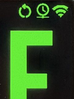
If the LCD cannot be initialized, the clock prints diagnostics to stdout as a last resort.
The software takes into consideration daylight saving time (DST) and timezones as configured in flash. Timezones are configured as hour/half-hour offsets matching those known across the globe. The following DST rules are available which covers all regions:
| Region / Pattern | DST Start Rule (Clocks go forward) | DST End Rule (Clocks go back) | Shift |
|---|---|---|---|
| None (Japan, India, Arizona, Hawaii) | Does not observe DST | Does not observe DST | 0 |
| North America (US, Canada) | 2nd Sunday in March at 02:00 | 1st Sunday in November at 02:00 | +1 Hour |
| Europe / UK (EU, UK, Switzerland) | Last Sunday in March at 01:00 UTC | Last Sunday in October at 01:00 UTC | +1 Hour |
| Australia (Most states) | 1st Sunday in October at 02:00 | 1st Sunday in April at 03:00 | +1 Hour |
| New Zealand | Last Sunday in September at 02:00 | 1st Sunday in April at 03:00 | +1 Hour |
| Chile | 1st Saturday in September at 24:00 | 1st Saturday in April at 24:00 | +1 Hour |
| Israel | Friday before the last Sunday in March | Last Sunday in October at 02:00 | +1 Hour |
Configuration is stored in Flash and the clock will reconfigure itself when:
If factory reset is hed during boot, the clock will erase the stored flash configuration regardless of whether it is valid or not making holding the reset during normal operation harmless until the configuration is saved.
During configuration, the clock starts a Wi-Fi access point with the prefix Pico-Day-Clock-Setup and the last part of the Pico's MAC address. Connecting a device to this Wi-Fi network should start a captive portal, but if not, the clock's default IP address is 192.168.4.1 and you can direct your browser to http://192.168.4.1/. The following form configures the clock:
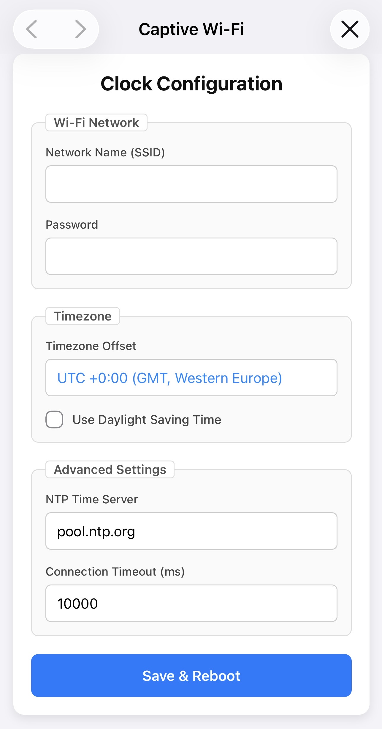
The minimum setup is a valid Wi-Fi SSID and password. If the password is incorrect, you must force a factory reset as the clock will try indefinitely to connect to the configured Wi-Fi.
The software is expected to build on Mac, Linux and Windows hosts and should be able to be imported into the Raspberry Pi Pico extension to Visual Studio Code. The Pico target build uses the standard Pico SDK tooling, but the native tests and coverage require LLVM for Clang and the coverage tools.
Tests for the core clock functionality and error handling is largely complete through some very basic mocking of the Pico SDK. The code for the mocking is by no means complete and is just the very minimum required to make the clock function and generate errors that might occur such as DNS timeouts.
The tests run on the host and assume Clang is available. Windows hosts are unsupported for testing as the host implementation of time_t is incompatible with the NTP implementation which assumes uses timestamps starting in 1900 and in turn this requires 64-bit time_t.
Automated CI is provided by GitHub runners.
On boot, all LCDs are initialized first and diagnostic messages are displayed on the LCD1 as Wi-Fi and then NTP is initialized. On success, the clock starts. If any error is unrecoverable, signaled by a status message in red, the clock will not start and the diagnostics will remain. If the diagnostics do not appear at all, there is a problem with the LCD connections or the LCD driver. The following CMake configuration is available for debug to the UART:
CLOCK_DEBUG_ENABLED: debug messages from the day of week clock itselfPICO_CYW43_ARCH_DEBUG_ENABLED: SDK built-in debug of Wi-FI connectionsLWIP_MALLOC_DEBUG: SDK built-in memory allocation debugLWIP_PROTOCOL_DEBUG: SDK built-in UDP debugThe pinout for the LCD is defined in config.h using a series of C macros LCD1_GPIO_xxx. The backlight is shared across all of the LCDs as there is no need to control the dimming of the LCDs individually.
| Pin to device mapping | Name | Pin | Pico | Pin | Name | Pin to device mapping |
|---|---|---|---|---|---|---|
| Debug Probe RX | GP0 | 1 | XXXXX | 40 | VBUS 5V | |
| Debug Probe TX | GP1 | 2 | XXXXX | 39 | VSYS 5V | DollaTek VIN |
| Debug Probe GND | GND | 3 | XXXXX | 38 | GND | LCD GND |
| LCD 1 chip select (CS) | GP2 | 4 | XXXXX | 37 | 3V3 En | |
| LCD 2 chip select (CS) | GP3 | 5 | XXXXX | 36 | 3V3 Out | |
| LCD 3 chip select (CS) | GP4 | 6 | XXXXX | 35 | ADC VRef | |
| LCD 4 chip select (CS) | GP5 | 7 | XXXXX | 34 | GP28 A2 | |
| GND | 8 | XXXXX | 33 | ADC Gnd | ||
| LCD 5 chip select (CS) | GP6 | 9 | XXXXX | 32 | GP27 A1 | |
| LCD 6 chip select (CS) | GP7 | 10 | XXXXX | 31 | GP26 A0 | |
| LCD 7 chip select (CS) | GP8 | 11 | XXXXX | 30 | RUN | |
| Factory reset | GP9 | 12 | XXXXX | 29 | GP22 | |
| GND | 13 | XXXXX | 28 | GND | ||
| Shared clock (CLK) | GP10 | 14 | XXXXX | 27 | GP21 | |
| Shared MOSI (DIN) | GP11 | 15 | XXXXX | 26 | GP20 | |
| Shared reset (RST) | GP12 | 16 | XXXXX | 25 | GP19 | |
| Shared backlight (BL) | GP13 | 17 | XXXXX | 24 | GP18 | |
| GND | 18 | XXXXX | 23 | GND | ||
| Shared data/command (DC) | GP14 | 19 | XXXXX | 22 | GP17 | |
| Diagnostic LED | GP15 | 20 | XXXXX | 21 | GP16 |
The LCD module expects a 3.3V supply and the datasheet for the Waveshare 1.47inch LCD indicates that the backlight draws 60-90mA. All the LCDs can therefore be driven by a single voltage regulator such as the DollaTek 1117:
The BL backlight pin of the LCD module is not the actual LCD backlight; it is a control pin to the LCD module's TXB0108PWR level shifter so can also be shared across all LCDs and, like the other control signals, driven directly from the Pico.
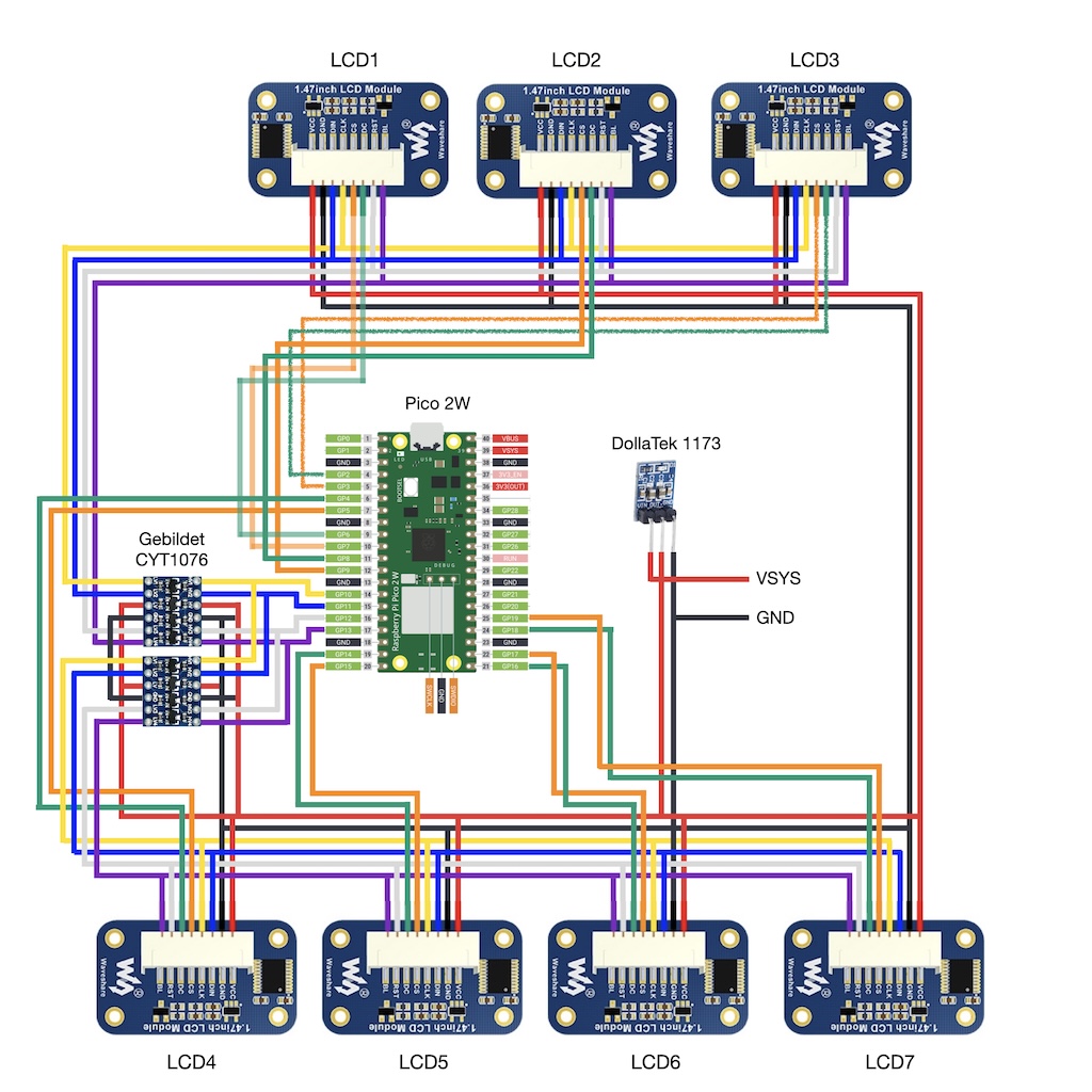
The Pico has insufficient drive strength to drive the control signals of 7 LCDs simultaneously, so a logic level converter with the VA and VB tied to 3V3 is used to increase the drive strength and buffer between the Pico and the LCDs. Care must be taken to choose a level shift with sufficient drive strength; a single TXB0108 proved insufficient and the final design uses two four-channel Gebildet CYT1076 level shifters. One CYT1076 drives the day of week LCDs (LCD1-3) and the other the time LCDs (LCD4-7).
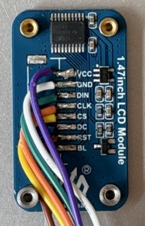
I chose the Waveshare LCD because it comes with a socket that has a wired plug with 2.54mm pin connectors for easy prototyping. For the final clock, this connector gets in the way of the wires hiding neatly behind the LCD. There are 172x320 LCD displays that are based on the ST7789 that come with an FPC connector which is neatly connected on the narrow edge of the display. The bare LCD with the FPC connector has the disadvantage for the hobbyist that you need to add a ZIF socket and then break that out into something with a wider pitch to solder. The connector on the Waveshare board can be desoldered using solder braid and the connector carefully snipped off using flush snippers. The Waveshare module also has 2mm brass mounting holes which makes mounting the LCDs securely simpler. The main drawback of the approach is that the read of the LCD is quite messy, but the intended use is for a wall-mounted clock. The soldered connections look like this (please forgive the terrible soldering skills; I am out of practice):
The glass domes appear to be referred to as "glass dome cloche covers with cork bases" and are available from Chinese manufactures on sites like TEMU. Since the class is reasonably heavy 2mm thick glass, the 25mm domes are too narrow in the internal diameter for the LCD so 28mm domes are required. Unfortunately 71mm long so they need to sit about 25mm below the top of the clock so that the LCDs are comfortable in the upper section of the dome. The domes sit inside a 4mm brass frame to which the LCDs can be held using M2 machine screws:
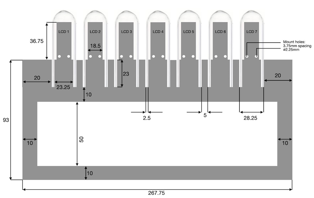
The brass frame is laser cut from 4mm brass using a CAD file that is generated using scripts/generate-dxf.py. Assuming CMake has generated the Python virtual environment in the build folder, you can build the DXF file (generated/clock_brass.dxf) using:
source build/scripts_venv/bin/activate
pip install ezdxf
python3 scripts/create-cad-drawing.py
It's also possible to generate a 3D model using Python for use as a 3D printing prototype to check that that everything aligns correctly:
source build/scripts_venv/bin/activate
pip install cadquery cadquery-ocp
python3 scripts/create-3d-model.py
The brass frame is then sandwiched between two rectangular woden boxes with no lids. The USB power cable is fed through one box and plugs into the Pico's USB port which simplifies the electrical design.
ST7789 init and driver code is derived from the Waveshare Sample Demo for the Waveshare 1.47inch LCD. The driver is licensed by the Waveshare team under an MIT license.
NTP driver code is derived from pico_ntp_client in the Raspberry Pi Pico SDK Examples which is licensed under a BSD license.
The access point and associated DHCP/DNS server are derived from pico_access_point in the Raspberry Pi Pico SDK Examples which is licensed under a BSD license.
Variable width fonts replace the fixed-width fonts in the Waveshare examples, but the C data structures are ultimately derived from work by STMicroelectronics licensed under the 3-clause BSD license.
The digit fonts included in the repository are Bebas Neue Regular which is licensed under the Open Font License, and Oswald which is also licensed under the Open Font License.
The text font used in display diagnostics during boot is Roboto Medium which is licensed under the Open Font License.
Icons in this project are derived from Google Material Design Icons, which are licensed under the Apache License 2.0. The icons have been resized and converted to C bitmaps for use in this project, and new icons have been derived to addition status badges.
| Qty | Value | Footprint | References |
|---|---|---|---|
| 1 | AMS1117-3.3 | Package_TO_SOT_SMD:SOT-223-3_TabPin2 | U1 |
| 1 | AO3400A | Package_TO_SOT_SMD:SOT-23 | Q2 |
| 1 | RaspberryPi_Pico | Module_RaspberryPi_Pico:RaspberryPi_Pico_Original_SMD | CPU1 |
| 1 | SN74LVC245N | Package_SO:TSSOP-20_4.4x6.5mm_P0.65mm | LEV1 |
NuttyShell/NuttyBadge
NuttyBadge: A NuttyShell crafted multi-tool. Opensourced Hardawre and Software


0xjmux/iot_leddriver_hw
ESP32-based WS2812B LED Strip Driver PCB, designed for music visualization


Churrosoft/OpenEFI-PCB
Coleccion de PCB y planos recomendados para montar una OpenEFI


chl33/Plant133
Firmware, circuit design, and 3D-printable components for an automated plant-watering system.
4 parts, built around the AMS1117-3.3 and AO3400A. The full list of its parts is on this page, with links to each part's symbol and footprint where PCBKit's library has them.
From the masaccio/picow_day_clock repository on GitHub, at the commit this page was made from: the board is kicad/pico_dow_clock/pico_dow_clock.kicad_pcb and its schematic kicad/pico_dow_clock/pico_dow_clock.kicad_sch. PCBKit opens the board in the browser, with nothing to install.
Its repository publishes it under the MIT licence: you may reuse it on that licence's terms (keep the author's notice, and for a copyleft licence share your changes alike).