2 layers25 × 14.7 mm
Mini pcb-3-to-5V booster
martinberlin/H-cinread-it8951
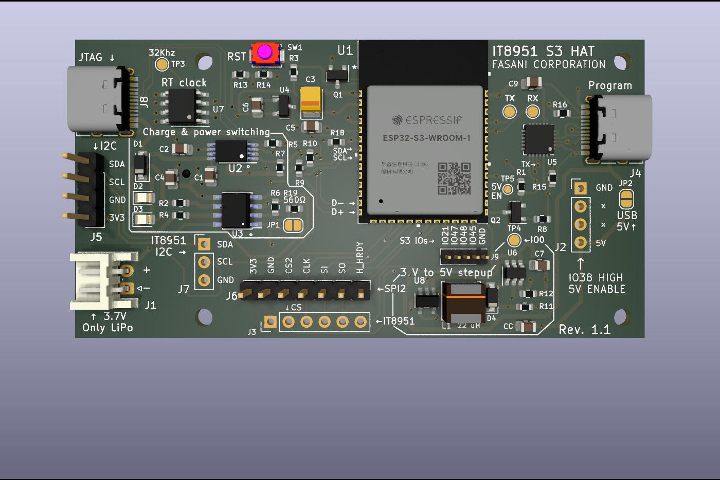
CINWRITE pcb is the Hardware repository for the HAT that provides GoodDisplay DEXA-C097 controller a fast way to talk SPI and 5V boost converter.
9 parts12

 martinberlin/H-cinread-it895112
CINWRITE pcb is the Hardware repository for the HAT that provides GoodDisplay DEXA-C097 controller a fast way to talk SPI and 5V boost converter. The goal of this HAT is to provide WiFi, Bluetooth, RTC and extra I2C connector for sensors
IT8951-HAT is an open-source printed circuit board by martinberlin, from the martinberlin/H-cinread-it8951 repository on GitHub. It is a 2-layer board of 83.2 × 42.1 mm with 65 parts on 90 nets, routed with 694 tracks and 80 vias.
It is built around the ESP32-S3-WROOM-1-N8, MT3608 and DS3231MZ/V+, with the TP4056, BC817 and CR1220-2 among its other parts. Its parts include 18 resistors, 10 connectors, 9 capacitors, 8 ICs and 4 diodes. It belongs with the lEDs and displays and radio and wireless boards and the ESP32 boards of this library.


Hardware repository for Cinwrite PCB, a HAT for 9.7 inch parallel epaper display controller DEXA-C097 sold by Good display which uses IT8951 as epaper timings controller and display engine.
This hardware is open source and you can use it commercially or modify it for your own purpouses according to the terms specified in the License. The only restriction is that it should be not mass produced and not sold without the permission of the Licensor.
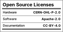
Licensed by:

We only ask to be notified if you make a product based on this so we can showcase it as a success story. Collaborations and corrections on any terms including lowering consumption are welcome, please make an Issue, or feel free to contact me to the email in my github profile.
The goal of this HAT is to provide:
You can get the produced and tested Cinwrite board in Tindie and at the same time you collaborate with our research.
Even if you plan to send a batch for fabrication, we strongly recommend to get one first, so you collaborate with my work. But more importantly you can test the hardware to evaluate if it suits your project. I don't have big quantities at the moment but you can get one at:
Both have similar prices. We can ship to all European countries and also to China mainland. Please check the hardware notices and also the DEXA-CO97 board from GOOD-DISPLAY if you want to drive a 1200x825 9.7" epaper display.
Cinread early revisions that Goodisplay is selling need a small very tiny bridge in the resistances at the side of SPI. Also the Silkscreen has an error and SI is swapped by CLK. Please refer to the following image to the correct SPI labels:
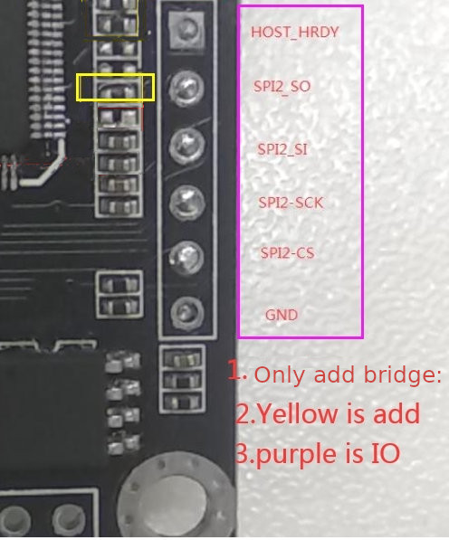
Important: Please mind that the Cinread PCB has the SPI labels wrong. And that it needs a 0 Ω 0402 in the position marked as yellow. 6th counting from below at the SO Slave Output pin is please check the image carefully and place it in the right side. This will enable SPI.
UPDATE: On last point about the 0 Ω resistance just check that is there. But Good-Display is selling this with the hardware modification done so SPI should be running as it should.
Provided by colleagues Larry Bank and Lovyan03
Referenced from this page in Espressif documentation
GPIO19 D-

GPIO20 D+

5V -> V_BUS
This second USB will also enable DFU mode to flash the Microcontroller.
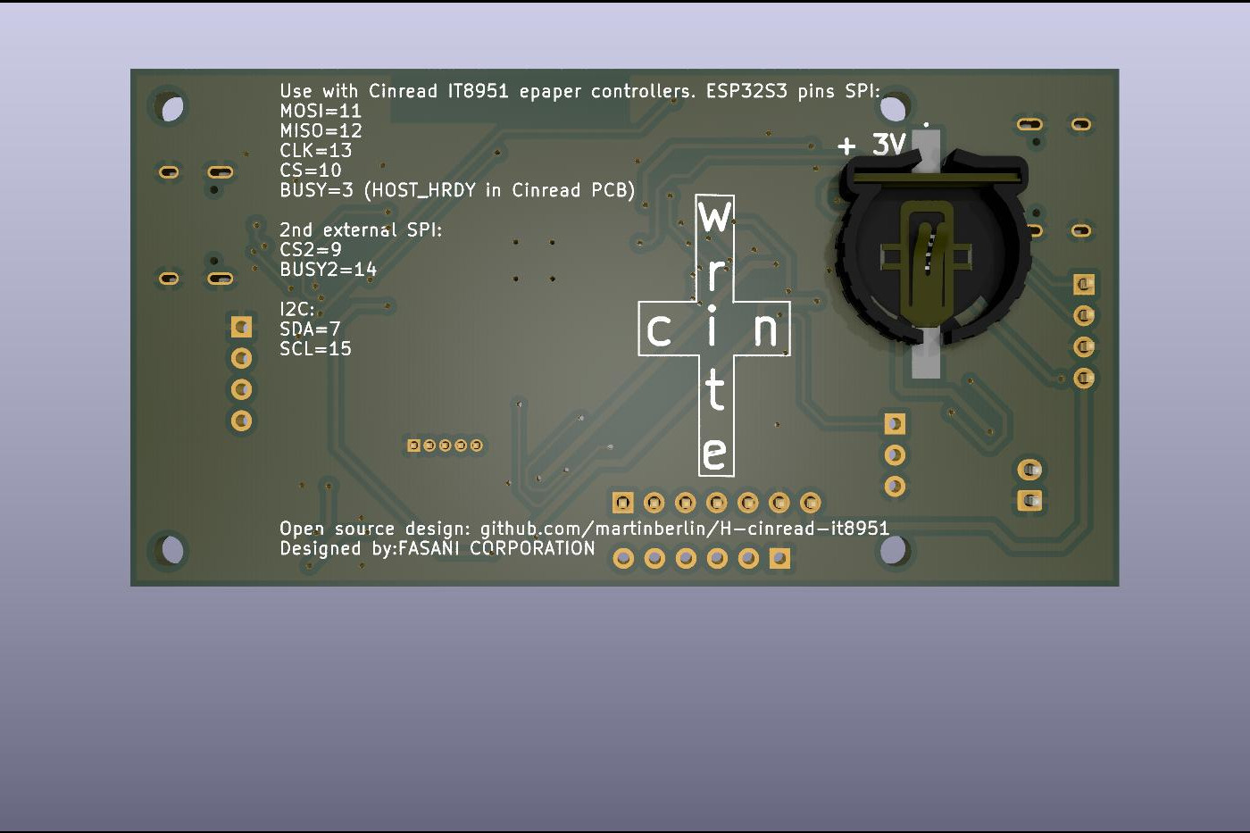
On my first tests to implement this using an Espressif ESP32-S3-WROOM-1U-N8R2 module with 2MB PSRAM I used the following GPIOs:
CONFIG_EINK_SPI_MOSI=11
CONFIG_EINK_SPI_MISO=12
CONFIG_EINK_SPI_CLK=13
CONFIG_EINK_SPI_CS=10
CONFIG_EINK_BUSY=3
Note: Reset PIN is not needed and it's also not in Cinread PCB sold by Good display.
MISO pin should be connected and spi_3wire parameter for Lovyan GFX set to false, since it is in fact 4 wire SPI (CLK, MOSI, MISO)
This is using at the testing breadboard Lovyan GFX in their develop branch, since it reads the mem_address to write the image from SPI, hence using the master branch of the library it will not work or it will write the image incorrectly on the 9.7" display.
In case you want to test it earlier, please get a ESP32-S3-WROOM-1U-N8R2 and connect the 4 required SPI cables, plus 5V and GND making your own PCB.
Meet epaper weather station first project featuring this hardware and our test PCB.

| Qty | Value | Footprint | References |
|---|---|---|---|
| 5 | 10 K | Resistor_SMD:R_0603_1608Metric | R1, R3, R7, R8, R18 |
| 4 | MountingHole | MountingHole:MountingHole_2.5mm | H1, H2, H3, H4 |
| 3 | 100nF | Capacitor_SMD:C_0805_2012Metric | C1, C2, C4 |
| 2 | 10uF | Capacitor_SMD:C_0805_2012Metric | C5, C6 |
| 2 | 1N5817 | Diode_SMD:D_SOD-123 | D1, D4 |
| 2 | 22uF | Capacitor_SMD:C_0805_2012Metric | C7, C8 |
| 2 | 4.7K | Resistor_SMD:R_0603_1608Metric | R9, R10 |
| 2 | 5.1K | Resistor_SMD:R_0603_1608Metric | R15, R16 |
| 2 | 5K | Resistor_SMD:R_0603_1608Metric | R2, R4 |
| 2 | BC817 | Package_TO_SOT_SMD:SOT-23 | Q1, Q2 |
| 1 | 100 nF | Capacitor_SMD:C_0805_2012Metric | C9 |
| 1 | 110K | Resistor_SMD:R_0603_1608Metric | R11 |
| 1 | 15K | Resistor_SMD:R_0603_1608Metric | R12 |
| 1 | 160K | Resistor_SMD:R_0603_1608Metric | R14 |
| 1 | 22 uH | footprint:SWPA5040S282MT | L1 |
| 1 | 32Khz | TestPoint:TestPoint_Pad_D1.5mm | TP3 |
| 1 | 400 | Resistor_SMD:R_0603_1608Metric | R5 |
| 1 | 442K | Resistor_SMD:R_0603_1608Metric | R13 |
| 1 | 532530470 | footprint:MOLEX-I2C-532530470 | J10 |
| 1 | 560Ω | Resistor_SMD:R_0603_1608Metric | R19 |
| 1 | 5V_EN | TestPoint:TestPoint_Pad_D1.0mm | TP5 |
| 1 | 680Ω | Resistor_SMD:R_0603_1608Metric | R6 |
| 1 | AP22802AW5-7 | footprint:AP22802AW5-7 | U8 |
| 1 | BOOT | TestPoint:TestPoint_Pad_D1.5mm | TP4 |
| 1 | CP2102N-Axx-xQFN24 | Package_DFN_QFN:QFN-24-1EP_4x4mm_P0.5mm_EP2.6x2.6mm | U5 |
| 1 | CR1220 | footprint:CR12202ZX | BT1 |
| 1 | C_Polarized 100uF | Capacitor_Tantalum_SMD:CP_EIA-3528-21_Kemet-B | C3 |
| 1 | Conn_01x03_Female | Connector_PinHeader_2.54mm:PinHeader_1x03_P2.54mm_Vertical | J7 |
| 1 | Conn_01x04_Female | Connector_PinHeader_2.54mm:PinHeader_1x04_P2.54mm_Vertical | J5 |
| 1 | Conn_01x04_Male POWER | Connector_PinHeader_2.54mm:PinHeader_1x04_P2.54mm_Vertical | J2 |
| 1 | Conn_01x05_Female | Connector_PinHeader_1.27mm:PinHeader_1x05_P1.27mm_Vertical | J9 |
| 1 | Conn_01x06_Female | Connector_PinHeader_2.54mm:PinHeader_1x06_P2.54mm_Vertical | J3 |
| 1 | Conn_01x07_Female | Connector_PinHeader_2.54mm:PinHeader_1x07_P2.54mm_Vertical | J6 |
| 1 | DS3231MZ | Package_SO:SOIC-8_3.9x4.9mm_P1.27mm | U7 |
| 1 | ESP32-S3-WROOM-1-N8 | footprint:ESP32-S3-WROOM-1-N8 | U1 |
| 1 | GRE | LED_SMD:LED_0805_2012Metric | D2 |
| 1 | Jack-DC | Connector_JST:JST_EH_S2B-EH_1x02_P2.50mm_Horizontal | J1 |
| 1 | Jumper_2_Bridged | Jumper:SolderJumper-2_P1.3mm_Bridged_RoundedPad1.0x1.5mm | JP1 |
| 1 | Jumper_2_Open | Jumper:SolderJumper-2_P1.3mm_Open_RoundedPad1.0x1.5mm | JP2 |
| 1 | MCP1700-3302E_SOT23 | Package_TO_SOT_SMD:SOT-23 | U4 |
| 1 | MT3608 | Package_TO_SOT_SMD:SOT-23-6 | U6 |
| 1 | RED | LED_SMD:LED_0805_2012Metric | D3 |
| 1 | RESET | footprint:Alps_SKRK | SW1 |
| 1 | RX | TestPoint:TestPoint_Pad_D1.5mm | TP2 |
| 1 | TP4056 | tp4056:TP4056_SOP-8-PP | U3 |
| 1 | TPS2113APWR | footprint:TPS2113APW | U2 |
| 1 | TX | TestPoint:TestPoint_Pad_D1.5mm | TP1 |
| 1 | USB_C_JTAG | footprint:USB_C_Receptacle_HRO_TYPE-C-31-M-12 | J8 |
| 1 | USB_C_Programming | footprint:USB_C_Receptacle_HRO_TYPE-C-31-M-12 | J4 |
martinberlin/H-cinread-it8951
CINWRITE pcb is the Hardware repository for the HAT that provides GoodDisplay DEXA-C097 controller a fast way to talk SPI and 5V boost converter.

martinberlin/bistable-smart-switch
An epaper switch project with 2 PCBs, controller+touch, and 220AC to 3DC with Relay (Latch or solid-state)


arcticlula/Netscore
Device that keeps track of a volleyball's game score (points and sets). Ideally it should be mounted on the net, since it has a display on the front and back and buttons on the sides.

rowr111/blinky-badge-light
lighting badge with unique patterns and sound reactivity

Ruthvik-reddy-A/PCB-design-projects
Welcome to my curated collection of hardware design projects focused on practical, compact, and beginner-to-intermediate level printed circuit board (PCB) designs.

justinnova0915/fallout
ENDFIELD inspired hardware deck for tiling window managers.


cfdev/mSolarWeather
This project use the SparkFun weather meter kit and other sensors
It measures 83.2 × 42.1 mm and has 2 copper layers, 1.6 mm thick.
65 parts, built around the ESP32-S3-WROOM-1-N8, MT3608, DS3231MZ/V+ and TP4056. The full list of its parts is on this page, with links to each part's symbol and footprint where PCBKit's library has them.
From the martinberlin/H-cinread-it8951 repository on GitHub, at the commit this page was made from: the board is IT8951-HAT.kicad_pcb and its schematic IT8951-HAT.kicad_sch. PCBKit opens the board in the browser, with nothing to install.
Its repository states no licence, so its author keeps all rights: ask martinberlin before reusing the design.