
4 layers243.8 × 171.5 mm

 marsairforce/ds1307_breakout2
A simple breakout board for the DS1307 Real Time Clock IC, suitable for breadboarding and prototype work
Ds1307 breakout is an open-source printed circuit board by marsairforce, from the marsairforce/ds1307_breakout repository on GitHub. It is a 2-layer board of 20.3 × 10.2 mm with 7 parts on 8 nets, routed with 54 tracks and 6 vias.
It is built around the DS1307Z+. Its parts include 2 resistors, 2 connectors, 1 capacitor, 1 IC and 1 crystal. It belongs with the interfaces and adapters boards of this library.
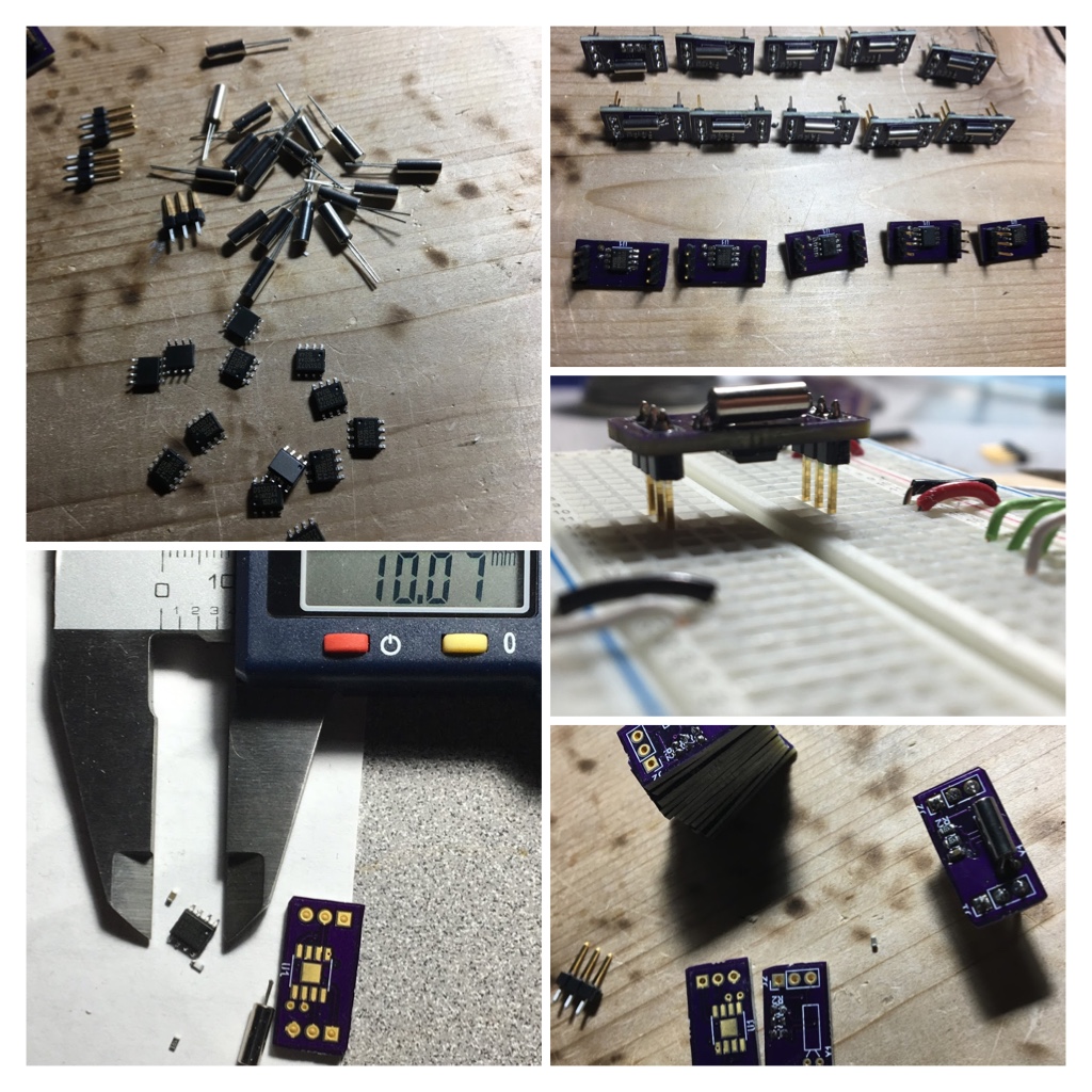
Why would you build a module, that costs you more, than existing breakout modules you can readily buy, that do more things? Well. to learn of course. I also had some parts in stock from AliExpress. Felt kind of silly to go order some break out boards when I could just build me some.
I wanted a smaller footprint size than the modules that existed, working at the time to build a tiny clock for the kids. I ended up using the adafruit breakout because i had it already, but for next time I wanted to be smaller. To do this I just didn't put the battery holder on the board, a pin to hook it up. So we have to provide our own battery. And I used components on both sides of the board. I don't really like the not-surface mount crystal oscillator, but again just using up some stock I happened to have here.
Schematics done using Kicad
Just using one of the existing DS1307 libraries for your platform should work. I don't really have my own library for this yet, I use the Adafruit one for Arduino.
The KiCad project for schematic and PCB layout are here.
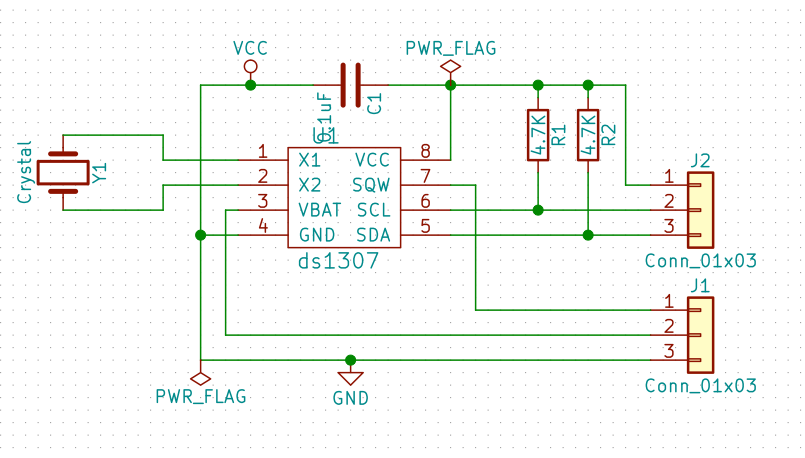
| Qty | Value | Footprint | References |
|---|---|---|---|
| 2 | 4.7K | Resistors_SMD:R_0603 | R1, R2 |
| 2 | Conn_01x03 | Pin_Headers:Pin_Header_Straight_1x03_Pitch2.54mm | J1, J2 |
| 1 | 0.1uF | Capacitors_SMD:C_0603 | C1 |
| 1 | Crystal | Crystals:Crystal_DS26_d2.0mm_l6.0mm_Horizontal | Y1 |
| 1 | ds1307 | Housings_SOIC:SOIC-8-1EP_3.9x4.9mm_Pitch1.27mm | U1 |

agranlund/raven
Homemade MC68060 + DSP56303 Atari-compatible computer. Hardware, firmware, and software stack

ExploreEmbedded/8051_DevelopmentBoard
Design files and sample code for 8051 development Ultra Boards

UzixLS/mist1010-board
10x10cm PCB variant of MIST FPGA project for G738/G706 enclosure


andykarpov/karabas-pro
FPGA based retrocomputer with FDD and HDD controllers

cropinghigh/zynq_a9_mb
Zynq 7z010 dev/main board based on components from Antminer S9 control board

It measures 20.3 × 10.2 mm and has 2 copper layers, 1.6 mm thick.
7 parts, built around the DS1307Z+. The full list of its parts is on this page, with links to each part's symbol and footprint where PCBKit's library has them.
From the marsairforce/ds1307_breakout repository on GitHub, at the commit this page was made from: the board is ds1307_breakout.kicad_pcb. PCBKit opens the board in the browser, with nothing to install.
Its repository states no licence, so its author keeps all rights: ask marsairforce before reusing the design.