4 layers59.6 × 85.6 mm
Recorder
zeeman-effect/pixel-snap-voice
A simple audio recording device that magnetically attaches to the back of a Pixel device
60 parts

 markusbichl/ADC_Silence_Detector
WCH CH32X033 based Silence detector for turntable to Toslink converter
ADC Silence Detector is an open-source printed circuit board by markusbichl, from the markusbichl/ADC_Silence_Detector repository on GitHub. It is a 2-layer board of 52.9 × 35.9 mm with 17 parts on 29 nets, routed with 101 tracks and 126 vias.
It is built around the AP2112K-3.3 and AP22804AW5. Its parts include 6 capacitors, 5 connectors, 3 ICs and 1 resistor.

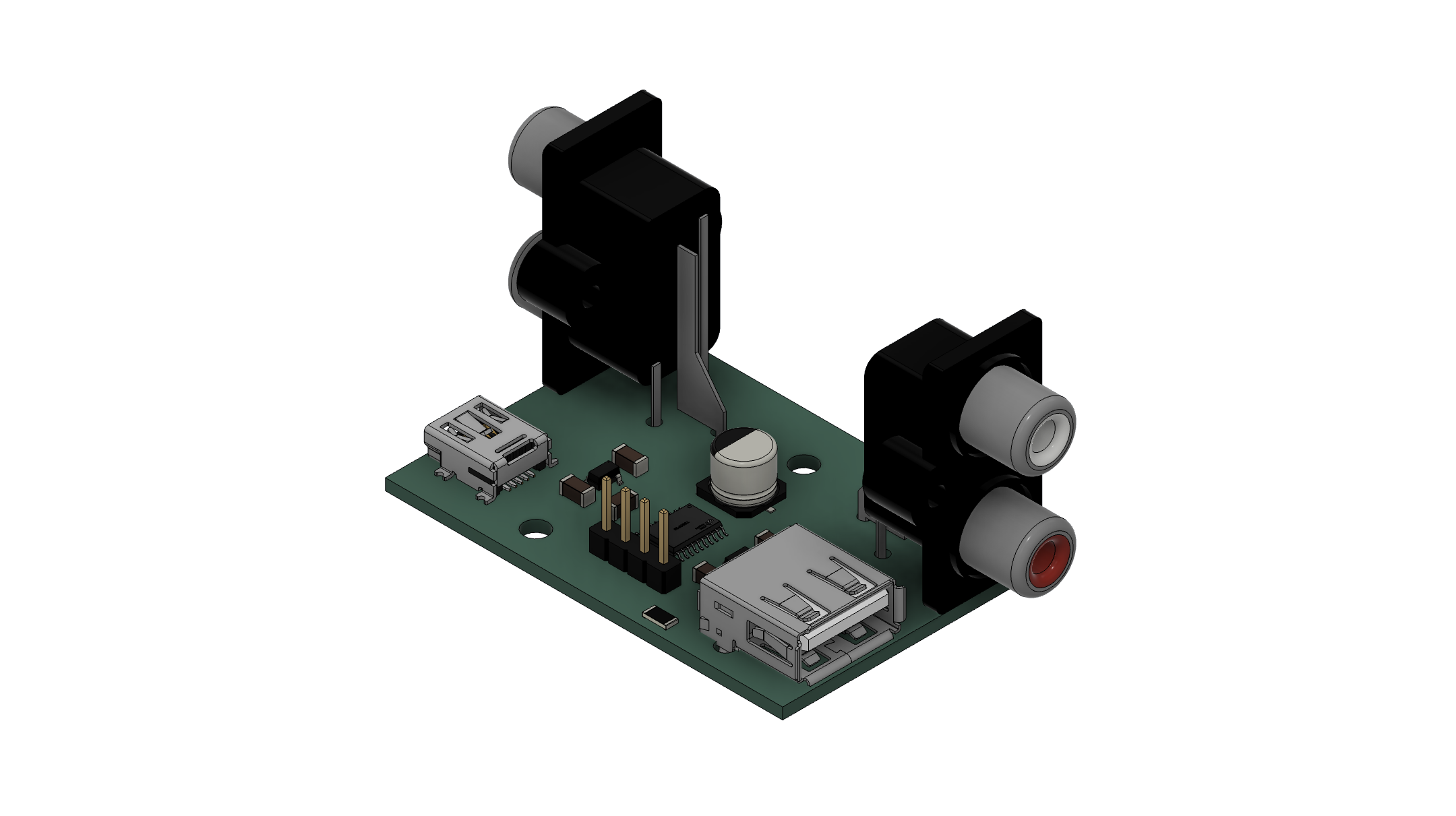
A compact embedded device that monitors analog audio input and automatically cuts power to a downstream USB ADC when silence is detected - eliminating idle noise and unnecessary power draw.
The ADC Silence Detector sits inline between your audio source and your USB ADC. It continuously monitors the analog audio signal on both left and right channels. As long as audio is present, the USB-A output port stays powered. Once silence is sustained, the device cuts USB power to the connected ADC, effectively turning it off without any manual intervention.
When audio resumes, power is restored and the downstream ADC comes back on automatically.
| Port | Type | Function |
|---|---|---|
| Power In | Mini-USB | 5 V power supply input |
| Audio In/Out L | RCA (double) | Left channel analog passthrough |
| Audio In/Out R | RCA (double) | Right channel analog passthrough |
| Power Out | USB-A | Switched 5 V output for the controlled ADC |
Audio Source ──► RCA In (L+R) ──► passthrough ──► RCA Out (L+R) ──► Downstream equipment
                      │
                      └──► ADC Level sensing (PA6 / PB0)
                                      │
                                      ▼
                              CH32X033 MCU
                                      │
                                      ▼
Mini-USB In ──────────────────► USB-A Out (switched via PB1)
The audio signal path is fully passive - the RCA inputs are wired straight through to the RCA outputs with no active components in the signal chain, preserving audio quality.
WCH CH32X033 - 32-bit RISC-V (rv32imacxw) running at 48 MHz from the internal HSI oscillator.
The firmware polls both ADC channels every 500 ms and takes the higher of the two readings as the current audio level. A hysteresis comparator prevents rapid toggling around the threshold:
| Condition | 12-bit ADC value | Action |
|---|---|---|
| Output OFF, level rises above | 20 | Turn USB-A output ON |
| Output ON, level falls below | 10 | Turn USB-A output OFF |
ADC channels:
| Pin | ADC Channel | Signal |
|---|---|---|
| PA6 | CH6 | Left channel level |
| PB0 | CH8 | Right channel level |
Output pin: PB1 drives the USB-A power switch.
SW
  User/
    main.c                      - application logic (ADC poll loop, hysteresis, GPIO control)
    system_ch32x035.c           - clock initialisation
    ch32x035_it.c               - interrupt handlers (unused stubs)
  Core/
    core_riscv.c/h              - RISC-V core support
  Debug/
    debug.c/h                   - SDI printf (debug UART over single wire)
  Peripheral/
    src/  inc/                  - WCH standard peripheral library
  Startup/
    startup_ch32x035.S          - reset vector and startup code
  Ld/
    Link.ld                     - linker script
PCB/
  ADC_Silence_detecor.kicad_pcb - KiCAD PCB
  ADC_Silence_detecor.kicad_sch - KiCAD Schematic
  jlcpcb/                       - Gerber files
CAD/
  case.stl                      - STL file of a simple Case
  ADC_Silence_detector.step     - STEP file of the populated PCB
  ADC_Silence_detector.stl      - STL file of the populated PCB
Demo
  ADC_Silence_detector.jpg      - Photo of the finished build
PCB_populated.png - Rendering of the populated PCBobj build configuration and click Build (or press Ctrl+B)..hex to the CH32X033.Debug output is available over SDI (single-wire debug interface) at 115200 baud and prints the raw ADC level on every poll cycle.
Peripheral library files are copyright Nanjing Qinheng Microelectronics Co., Ltd. Application code is released under the same terms - see individual file headers for details.
| Qty | Value | Footprint | References |
|---|---|---|---|
| 3 | 1u | Capacitor_SMD:C_1206_3216Metric_Pad1.33x1.80mm_HandSolder | C1, C2, C4 |
| 2 | 100n | Capacitor_SMD:C_1206_3216Metric_Pad1.33x1.80mm_HandSolder | C3, C5 |
| 2 | Conn_Coaxial_x2 | Connector_Coaxial:BNC_Win_364A2x95_Horizontal | J1, J2 |
| 2 | MountingHole_3.2mm_M3_Pad | MountingHole:MountingHole_3.2mm_M3_Pad | MH1, MH2 |
| 1 | 10k | Resistor_SMD:R_1206_3216Metric_Pad1.30x1.75mm_HandSolder | R1 |
| 1 | 120u | Capacitor_SMD:CP_Elec_6.3x5.8 | C6 |
| 1 | AP2112K-3.3 | Package_TO_SOT_SMD:SOT-23-5_HandSoldering | U2 |
| 1 | AP22804AW5 | Package_TO_SOT_SMD:SOT-23-5 | U3 |
| 1 | Conn_01x04_Pin | Connector_PinHeader_2.54mm:PinHeader_1x04_P2.54mm_Vertical | J4 |
| 1 | USB_A | Connector_USB:USB_A_Connfly_DS1095 | J5 |
| 1 | USB_B_Mini | Connector_USB:USB_Mini-B_Wuerth_65100516121_Horizontal | J3 |
| 1 | ~ | CH32X033:TSSOP-20_L6.5-W4.4-P0.65-LS6.4-BL | U1 |
zeeman-effect/pixel-snap-voice
A simple audio recording device that magnetically attaches to the back of a Pixel device

alvarop/debugotron
Debugotron is a collection of debugging/automation tools I've wanted in the past but didn't have access to. Currently, the tools include:

dmanla/SecureConnectivityDevelopmentPlatform
A development platform which provides secure connectivity and data logging support while maintaining compatibility with Arduino-Mega hardware and software.


si-nalsal/pcb-mantis
A servo-based UAV flight controller built around the STM32H743IIK6 (Cortex-M7, UFBGA-201, 0.65 mm pitch). The board distributes power to a fixed-wing/multirotor airframe with 16 PWM servo outputs, redundant IMU and…

XyrusB2010/XYmatics-E64
A 5-axis Klipper mainboard, powered by a Raspberry Pi Compute Module and STM32F407

FrameworkComputer/ExpansionCards
Reference designs and documentation to create Expansion Cards for the Framework Laptop

It measures 52.9 × 35.9 mm and has 2 copper layers, 1.6 mm thick.
17 parts, built around the AP2112K-3.3 and AP22804AW5. The full list of its parts is on this page, with links to each part's symbol and footprint where PCBKit's library has them.
From the markusbichl/ADC_Silence_Detector repository on GitHub, at the commit this page was made from: the board is PCB/ADC_Silence_detector.kicad_pcb and its schematic PCB/ADC_Silence_detector.kicad_sch. PCBKit opens the board in the browser, with nothing to install.
Its repository states no licence, so its author keeps all rights: ask markusbichl before reusing the design.