2 layers178.3 × 100.1 mm

 mariosgit/VFD27
Drivers for a bunch of VFD displays, like the MN12832, ...
VFD Power is an open-source printed circuit board by mariosgit, from the mariosgit/VFD repository on GitHub, published under the MIT licence. It is a 2-layer board of 83.5 × 27.9 mm with 24 parts on 17 nets, routed with 164 tracks and 31 vias.
It is built around the XL6009, ZXBM5210-S and 74132DC, with the DR125 among its other parts. Its parts include 8 capacitors, 5 resistors, 3 ICs, 3 inductors and 2 diodes. It belongs with the lEDs and displays boards of this library.

To edit a schematic/pcb, open the .pro file first (double click) KiCad needs this to handle sch/pcb together, otherwise u get wiered errors when updating pcb from schematic.
| front | back |
|---|---|
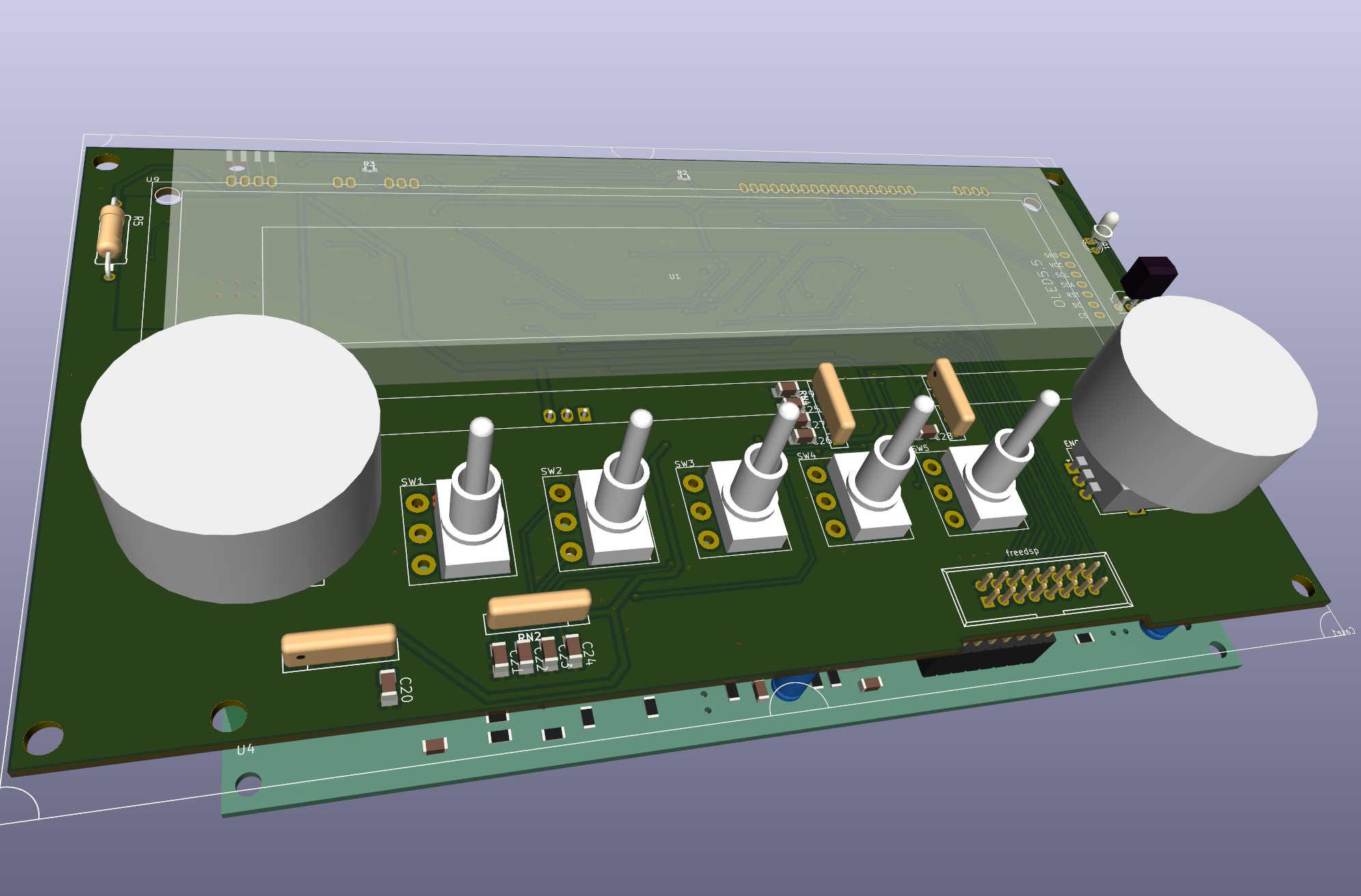 | 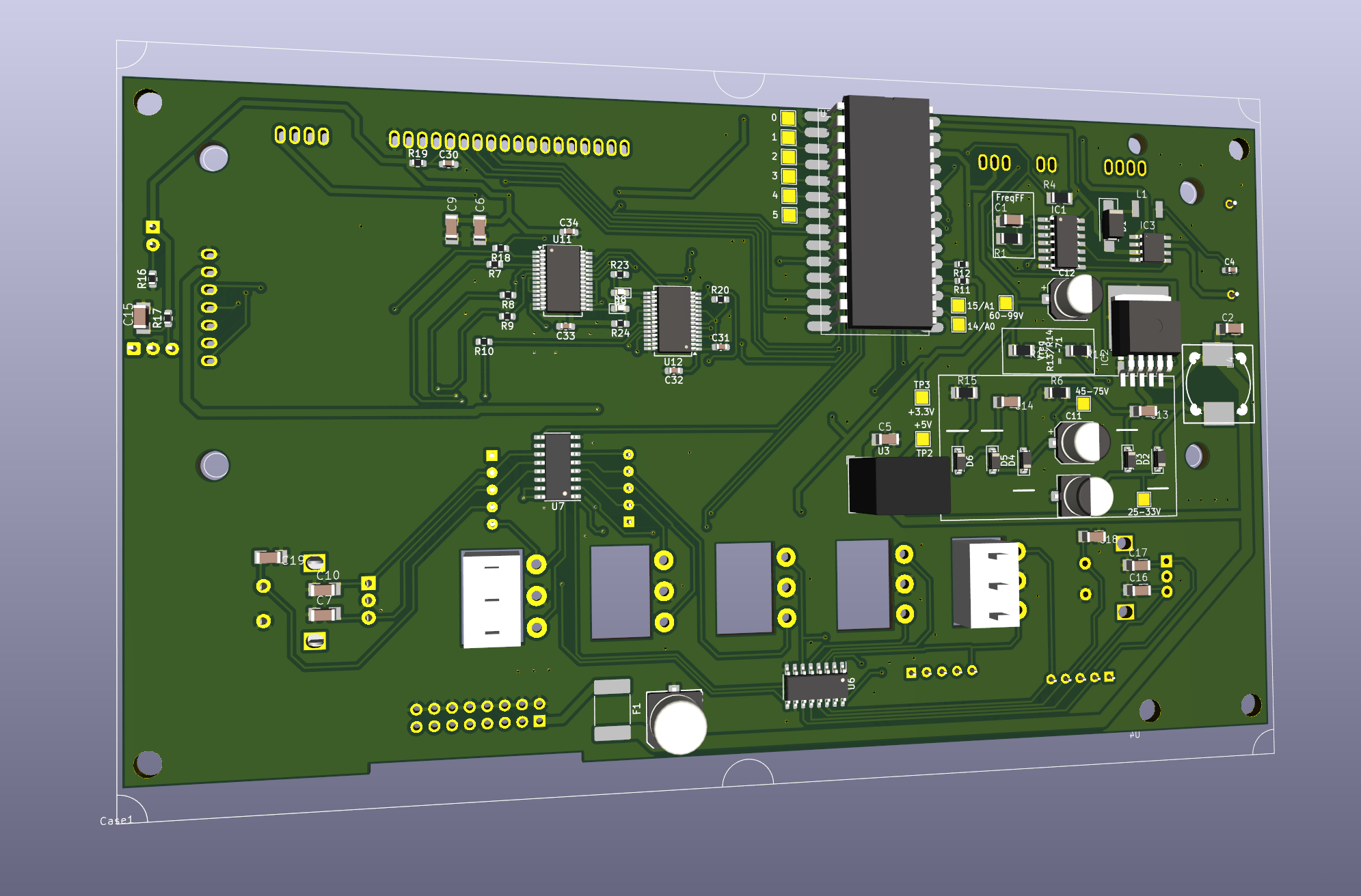 |
A Panel with that display and an Teensy4.
Intended Use: Graphical EQ. The bottom PCB is a FreeDSP-AllInOne.
Contains
Tested, has bugs... Can be patched to work somewhat.
Test audio connection to/from teensy I2S slave ! Can it do USB playback ? T3.2 or T4.0 ?
FreeDSP-AIO flaws ✅
| front | back |
|---|---|
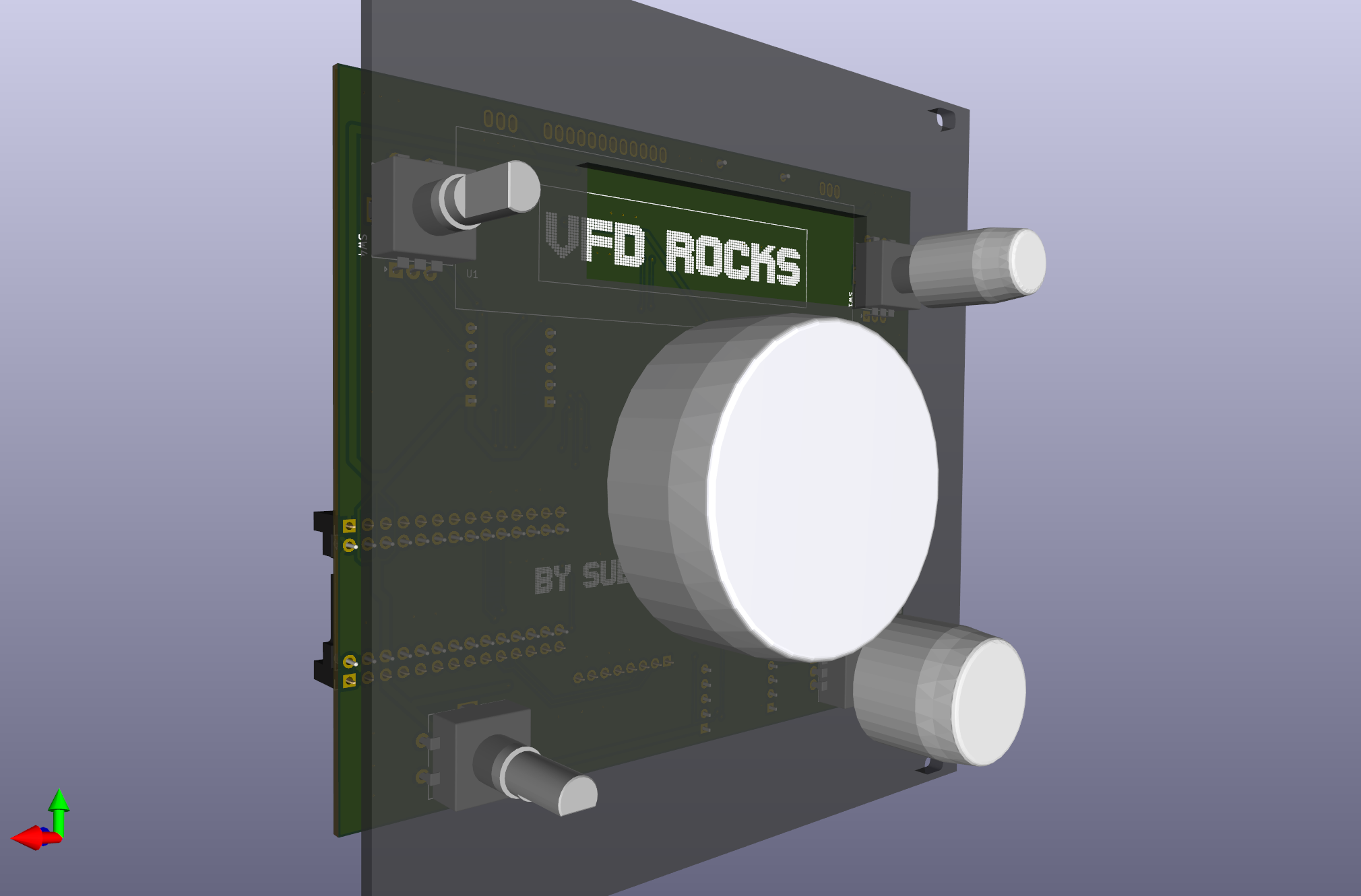 | 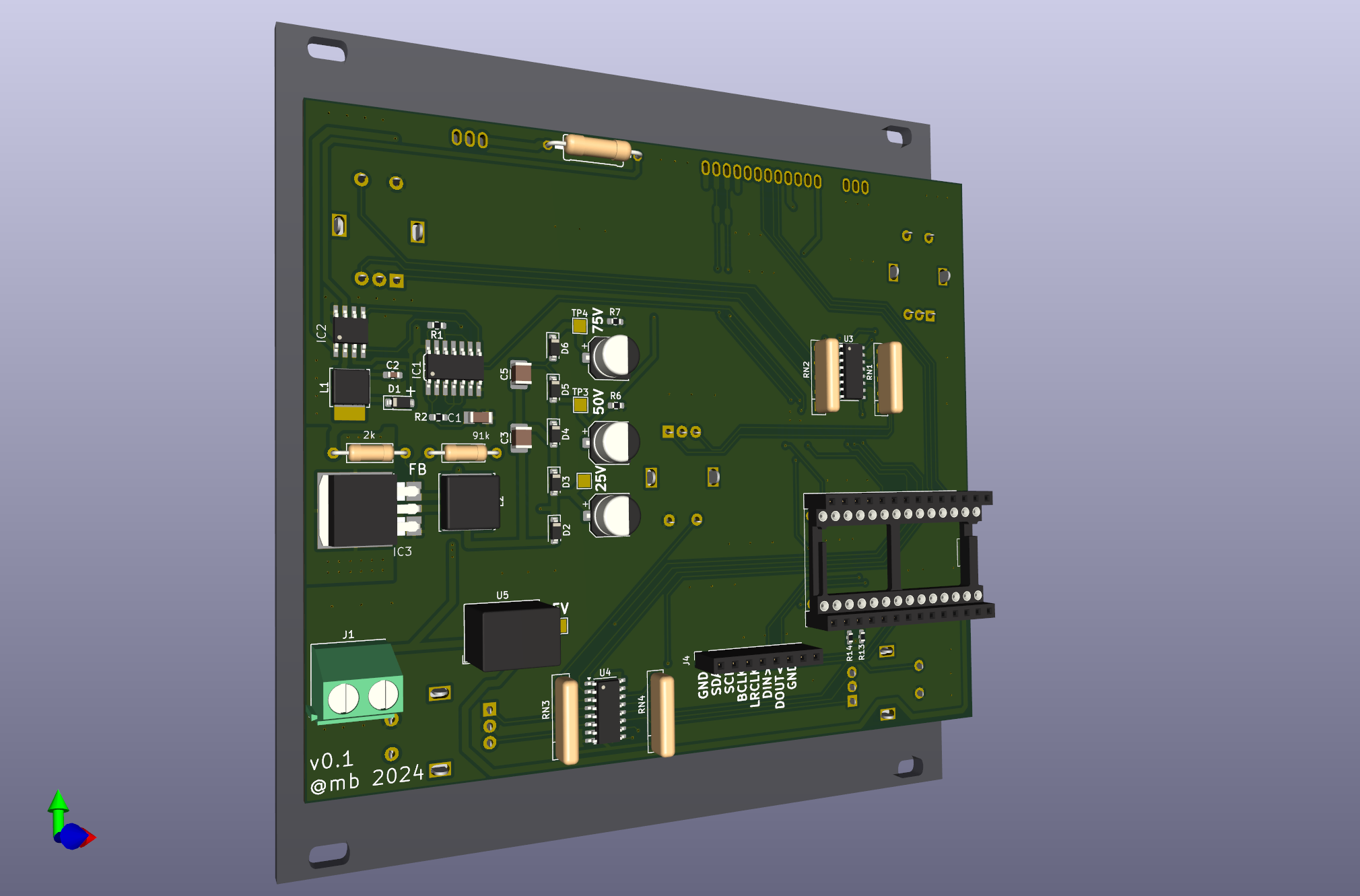 |
Eurorack 24U format - 12cm width. Made for some very specific recycled receiver knobs.
Batch v0.1 ordered.
| "Id" | "Designator" | "Footprint" | "Quantity" | "Designation" |
|---|---|---|---|---|
| 15 | "U3,U4" | "SOIC-16_3.9x9.9mm_P1.27mm" | 2 | "74HC165" |
| 34 | "U1" | "MN12832L" | 1 | "~" |
| 30 | "U2" | "Teensy4.0" | 1 | "~" |
| 23 | "U5" | "Converter_DCDC_RECOM_R-78E-0.5_THT" | 1 | "R-78B5.0-2.0" |
| 29 | "IC2" | "SO8" | 1 | "ZXBM5210" |
| 17 | "IC1" | "SO14" | 1 | "74132D" |
| 18 | "IC3" | "TO263-5" | 1 | "XL6009" |
| 2 | "D5,D4,D3,D2" | "D_SOD-123" | 4 | "1N4448W" |
| 16 | "D1" | "D_SOD-123" | 1 | "1N5818" |
| 14 | "L1" | "L_Cenker_CKCS5020" | 1 | "SM-NE45" |
| 22 | "L2" | "L_Cenker_CKCS8040" | 1 | "22uH" |
| 1 | "C1" | "C1206" | 1 | "4.7n" (FF-Freq) |
| 10 | "C4" | "CP_Elec_6.3x5.8" | 1 | "47u/35v" |
| 12 | "C6" | "CP_Elec_6.3x5.8" | 1 | "4.7u/100v" |
| 13 | "C3,C5" | "C_1210_3225Metric_Pad1.33x2.70mm" | 2 | "1u/100v" |
| 33 | "C2" | "C_0603_1608Metric_Pad1.08x0.95mm" | 1 | "1u" |
| 4 | "R2,R1" | "R_0603_1608Metric_Pad0.98x0.95mm" | 2 | "2.7k" (R2-FF-Freq) |
| 5 | "RN4,RN3,RN1,RN2" | "R_Array_SIP5" | 4 | "R_Network04" |
| 25 | "R14,R13" | "R_0603_1608Metric" | 2 | "2.2k" |
| 11 | "R6" | "R_Axial 10mm" | 1 | "91k" |
| 24 | "R4" | "R_Axial_DIN0207_L6.3mm_D2.5mm_P10.16mm" | 1 | "91k" VoltReg |
| 31 | "R5" | "R_Axial_DIN0207_L6.3mm_D2.5mm_P10.16mm" | 1 | "2k" |
| 9 | "R3" | "0411_15" | 1 | "22" 5W |
| 35 | "SW3,SW2,SW1,SW4,SW5" | "RotaryEncoder_Alps_EC11E" | 5 |
Used Kicad 3d models:
Start more Kicad instances on MacOS:
open -n -a "kicad"| Qty | Value | Footprint | References |
|---|---|---|---|
| 2 | 100n | VFD-Power:C1206 | C2, C7 |
| 2 | 1u | VFD-Power:153CLV-0505 | C4, C8 |
| 2 | 2.7k | VFD-Power:R1206 | R1, R4 |
| 2 | DIODE-SMB | VFD-Power:SMB | D1, D2 |
| 2 | MA04-1 | VFD-Power:MA04-1 | FILLAMENT0, UNK50V0 |
| 1 | 1.5k | VFD-Power:R1206 | R2 |
| 1 | 10u | VFD-Power:153CLV-0807 | C3 |
| 1 | 22 | VFD-Power:0411_15 | R5 |
| 1 | 39 | VFD-Power:R1206 | R3 |
| 1 | 4.7n | VFD-Power:C1206 | C1 |
| 1 | 74132D | VFD-Power:SO14 | IC1 |
| 1 | C-EUC1206 | VFD-Power:C1206 | C5 |
| 1 | CPOL-EU153CLV-0807 | VFD-Power:153CLV-0807 | C6 |
| 1 | DR125 | VFD-Power:DR125 | L3 |
| 1 | MA06-1 | VFD-Power:MA06-1 | POWER0 |
| 1 | MS85 | VFD-Power:MS85 | L2 |
| 1 | SM-NE45 | VFD-Power:SM-NE45 | L1 |
| 1 | XL6009 | VFD-Power:TO263-5 | IC2 |
| 1 | ZXBM5210 | VFD-Power:SO8 | IC3 |
It measures 83.5 × 27.9 mm and has 2 copper layers, 1.6 mm thick.
24 parts, built around the XL6009, ZXBM5210-S, 74132DC and DR125. The full list of its parts is on this page, with links to each part's symbol and footprint where PCBKit's library has them.
From the mariosgit/VFD repository on GitHub, at the commit this page was made from: the board is PCB-KiCad/VFD-Power.kicad_pcb and its schematic PCB-KiCad/GP1294-Teens4.kicad_sch. PCBKit opens the board in the browser, with nothing to install.
Its repository publishes it under the MIT licence: you may reuse it on that licence's terms (keep the author's notice, and for a copyleft licence share your changes alike).

mariosgit/VFD
Drivers for a bunch of VFD displays, like the MN12832, ...

mariosgit/VFD
Drivers for a bunch of VFD displays, like the MN12832, ...


Artpel1805/Beerator
Le but du projet est de réaliser intégralement un robot capable de se déplacer, de chercher et d’attraper une canette (de bière ? 😶), relever sa couleur, puis de la déposer dans la zone de couleur correspondante.

cva68/ESPBreadboardRobot
Peripheral and breakout board for the ESP-32, with firmware designed for use with Microsoft MakeCode


Groupe-Projet-ESE/BeerRobot
Chelsea COMLAN - Alix HAVRET - Loïcia KOEHL - Quentin SIMON


Lazorme/Ludz-le-chat
The Lidar and motor drivers are in drvLIDAR and drvMotor, respectively.