
2 layers44.2 × 29.3 mm

 Marcus10110/SolarPowerInterrupter
Quick and dirty PCB that will turn OFF a relay when USB power is appled.
SolarPowerInterrupter is an open-source printed circuit board by Marcus10110, from the Marcus10110/SolarPowerInterrupter repository on GitHub. It is a 2-layer board of 27.9 × 33 mm with 21 parts on 19 nets, routed with 111 tracks and 14 vias.
It is built around the BSS138 and BSS84. Its parts include 8 resistors, 3 diodes, 3 transistors, 2 connectors and 2 fuses. It belongs with the power boards of this library.
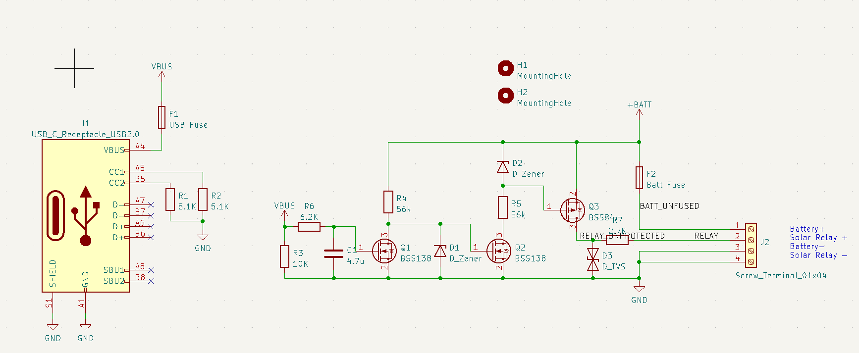
We will be charging the camp battery from both solar and generators. However, we do not want to attempt to charge the battery from two source at once, since they are unable to cooperate. To avoid this situation, the solar charger should automatically be disengaged when the generator is turned on. The solar charger connection instructions says to connect the battery before the solar panels. Therefore to turn off the solar charger, we should disconnect the panels from the solar charger.
This connection is approximately a maximum of 100V and 12A, DC.
The generator is detected by the presence of 5V from a USB charger connected to the generator.
When the 5V is not present, the relay should be conducting. The current required to turn on the relay will be provided by the battery.
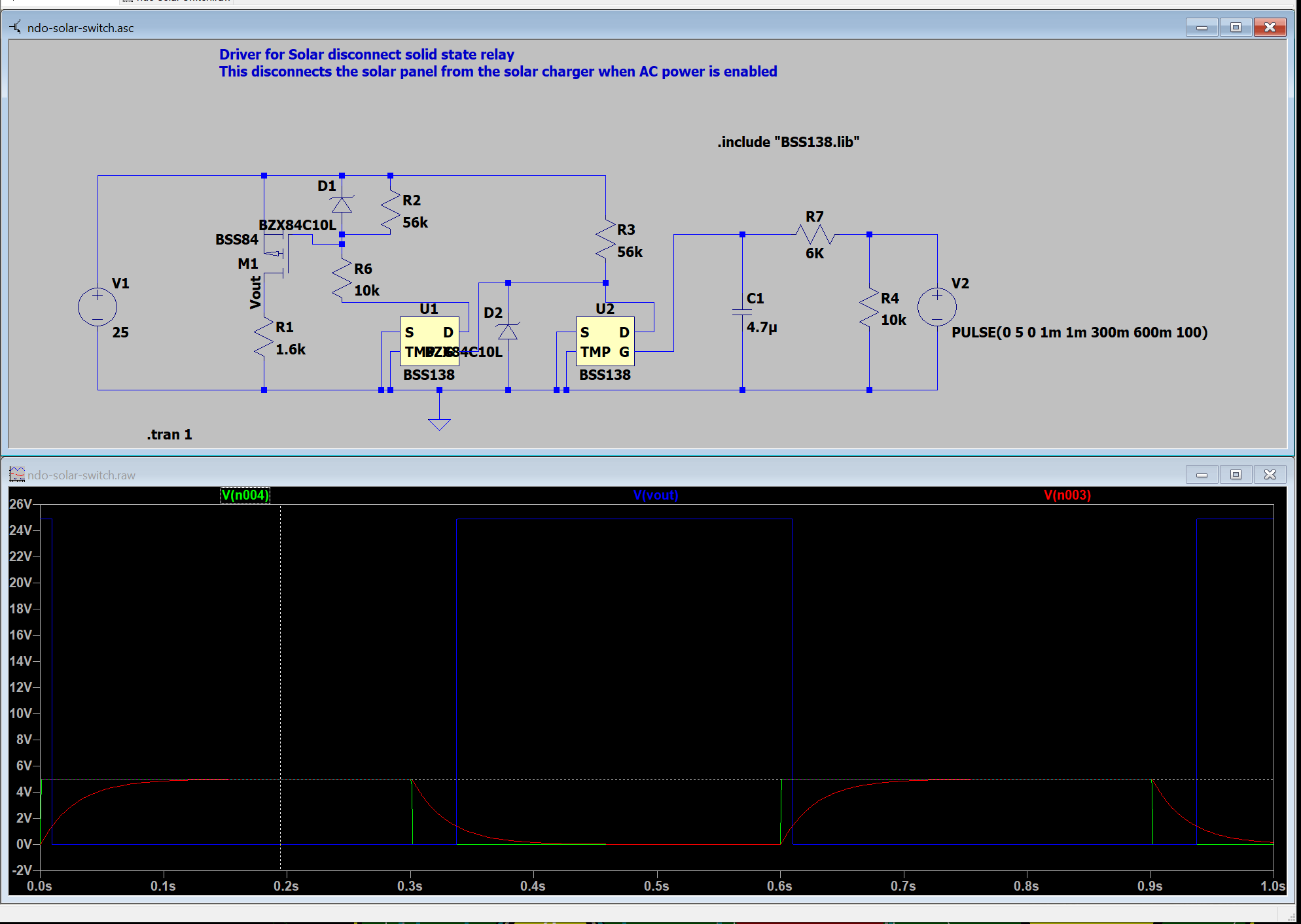
The solar power interrupter will effectively logically invert the input from the USB charger, and switch on/off the relay using the battery voltage and a high side switch.
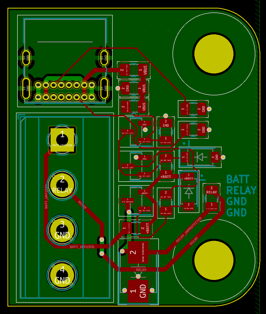
Note, some small changes have been made since these images were captured.
| Qty | Value | Footprint | References |
|---|---|---|---|
| 2 | 5.1K | Resistor_SMD:R_0805_2012Metric | R1, R2 |
| 2 | 56k | Resistor_SMD:R_0805_2012Metric | R4, R8 |
| 2 | BSS138 | Package_TO_SOT_SMD:SOT-23 | Q1, Q2 |
| 2 | D_Zener | Diode_SMD:D_SOD-123 | D1, D2 |
| 2 | MountingHole | MountingHole:MountingHole_4.3mm_M4 | H1, H2 |
| 1 | 10K | Resistor_SMD:R_0805_2012Metric | R3 |
| 1 | 10k | Resistor_SMD:R_0805_2012Metric | R5 |
| 1 | 2.7K | Resistor_SMD:R_0805_2012Metric | R7 |
| 1 | 4.7u | Capacitor_SMD:C_0805_2012Metric | C1 |
| 1 | 6.2K | Resistor_SMD:R_0805_2012Metric | R6 |
| 1 | BSS84 | Package_TO_SOT_SMD:SOT-23 | Q3 |
| 1 | Batt Fuse | Fuse:Fuse_0805_2012Metric_Pad1.15x1.40mm_HandSolder | F2 |
| 1 | D_TVS | Diode_SMD:D_SMB | D3 |
| 1 | Screw_Terminal_01x04 | TerminalBlock_Phoenix:TerminalBlock_Phoenix_MKDS-1,5-4_1x04_P5.00mm_Horizontal | J2 |
| 1 | USB Fuse | Fuse:Fuse_0805_2012Metric_Pad1.15x1.40mm_HandSolder | F1 |
| 1 | USB_C_Receptacle_USB2.0 | Connector_USB:USB_C_Receptacle_GCT_USB4085 | J1 |
It measures 27.9 × 33 mm and has 2 copper layers, 1.6 mm thick.
21 parts, built around the BSS138 and BSS84. The full list of its parts is on this page, with links to each part's symbol and footprint where PCBKit's library has them.
From the Marcus10110/SolarPowerInterrupter repository on GitHub, at the commit this page was made from: the board is solar power interrupter.kicad_pcb and its schematic solar power interrupter.kicad_sch. PCBKit opens the board in the browser, with nothing to install.
Its repository states no licence, so its author keeps all rights: ask Marcus10110 before reusing the design.


relic-se/PicoSynth_Sandbox-hardware
Raspberry Pi Pico digital synthesizer board with I2S stereo audio i/o, MEMS microphones, MIDI i/o, a capacitive keybed, 1602 display, 2 rotary encoders, and LiPo battery. Designed for use with CircuitPython and synthio.

jayanta525/dual-h-bridge
Dual H-Bridge Controller with IRF3205 and IR2104 MOSFET Driver, and with ATMega328P-AU PWM Controller

k-takata/PCB_avr_dx_unbricker
UPDI High Voltage programmer for AVR Dx/Ex series

biomurph/ILV2-7-5_VFD_Display
KiCAD circuit for a VFD Clock using the Popular ILV2-7/5 flat tube segmented nixie

LukasKropf/IO-Link-Shield
Das IO-Link-Shield für Arduino wurde an der BFH im Rahmen einer Projektarbeit erarbeitet. Dieses Repository enthällt alle wichtigen Daten zum Projekt.

mec-kon/weather_station
A simple weather station hardware (pcb files) for recording temperature, humidity, pressure and airquality.