
2 layers65 × 30 mm

 makrcat/EN.FO
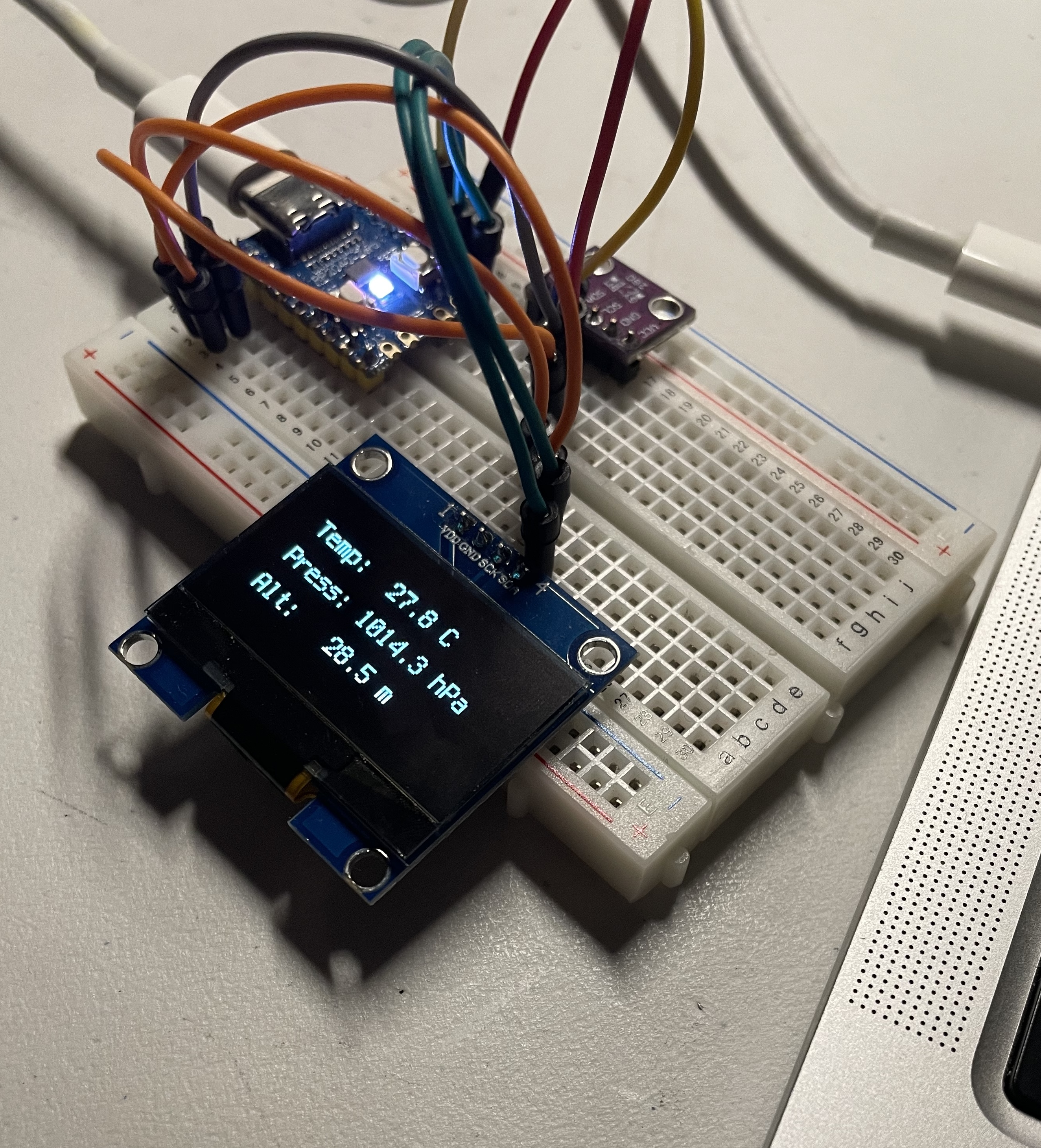
thing that uses BME680 for sensing altitude/weather for the outdoors
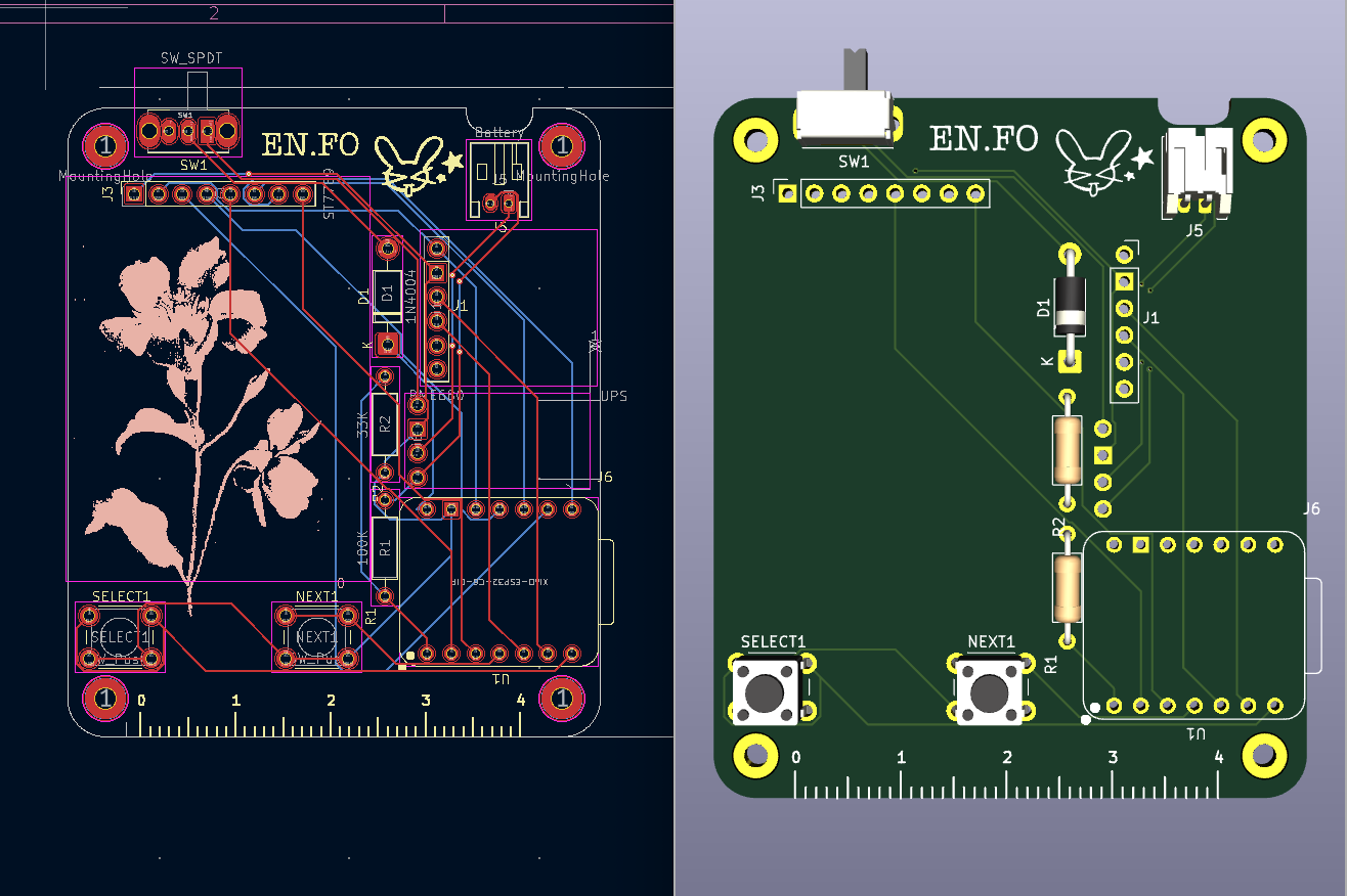
Thesensor is an open-source printed circuit board by makrcat, from the makrcat/EN.FO repository on GitHub. It is a 2-layer board of 56.1 × 66.3 mm with 17 parts on 21 nets, routed with 126 tracks and 5 vias.
It is built around the BME680. Its parts include 4 connectors, 2 resistors, 1 IC, 1 diode and 1 switch. It belongs with the ESP32 and RISC-V boards of this library.
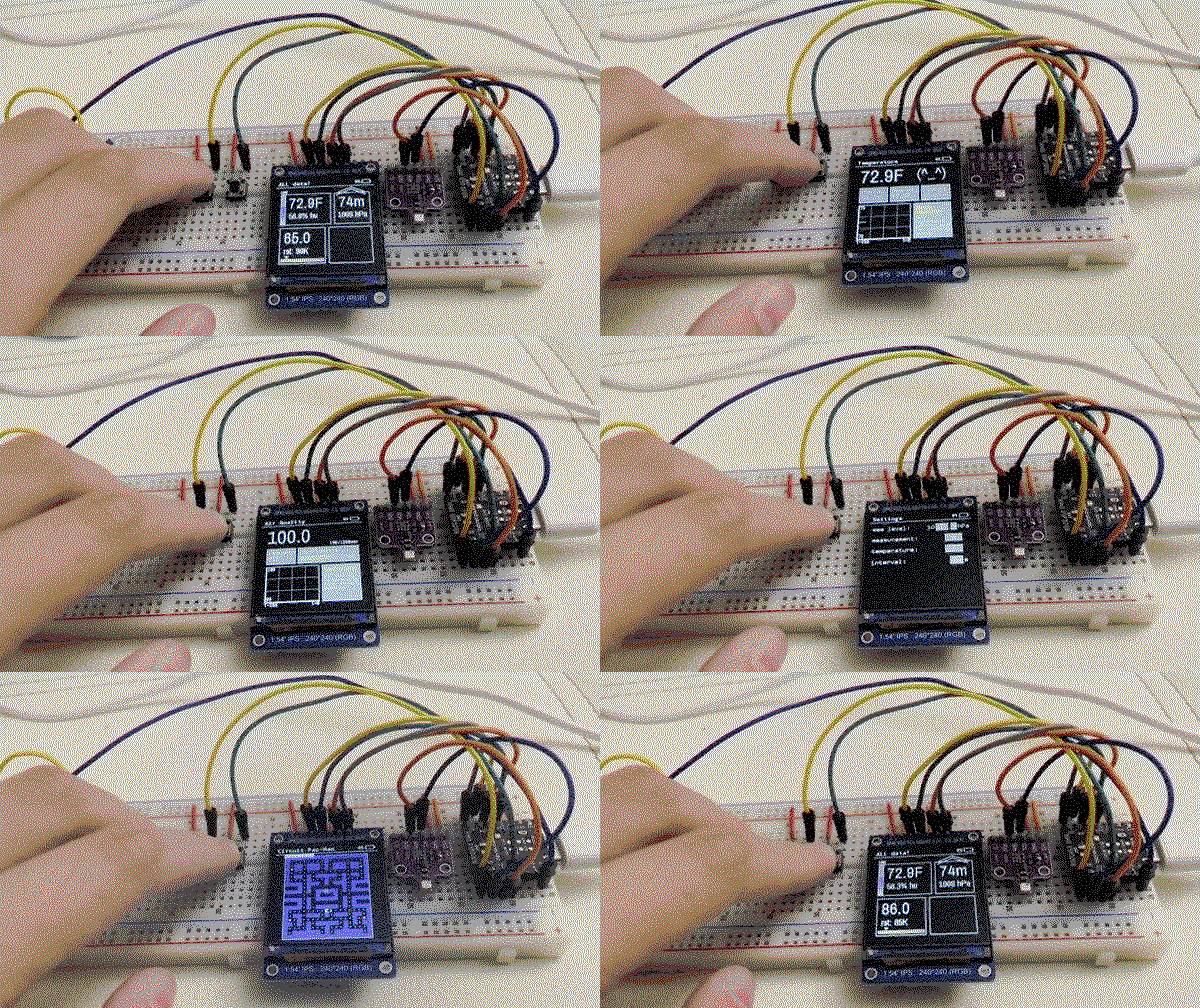
The EN.FO is a personal project for tracking the environment when outdoors. It measures altitude (pressure), temperature, humidity, and air quality through the BME680 chip. And it also has games now :3c
Around the end stages submitted to hack club stardance.
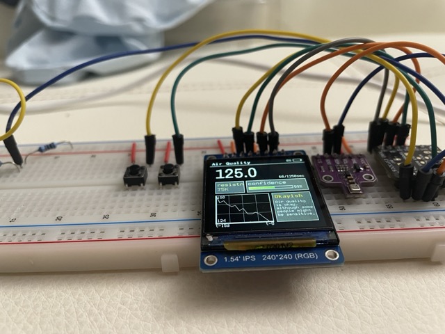
I found a BME680 in a store, and I'd seen people making these home weather station setups and using temperature sensors for their first projects. I thought it would be cool to be able to track the weather while outside too, like while hiking or going somewhere without wifi!
It would be pretty neat to get momentary values from a sensor for the surrounding area instead of looking online.
Materials:
Install circuitpython! Then,
I use vscode to program, but I used Thonny to handle the flashing.
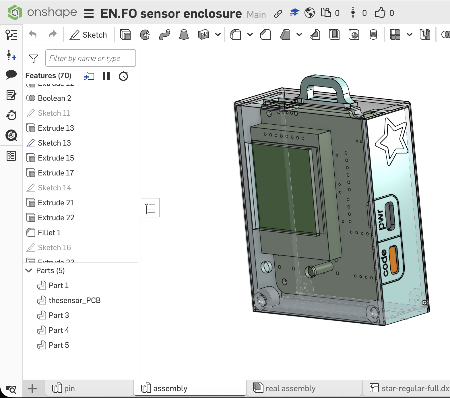
src, graphics, settings.json, logger.json, and fontsPCF, side by side on root/.Check if you are soldering the ESP-32 so that it's "bottom side up", or label-side up. The USB-C should be on the bottom. Same goes with the UPS module, make sure the USB-C is on the bottom. Or else you have to edit the CAD to match.
I wanted to test the UI quickly, so the computer simulation is for that. The data is simulated in mockIC.py.
⚠️ Important note!! Open the firmware folder by itself! Otherwise, vscode will read the file paths incorrectly.
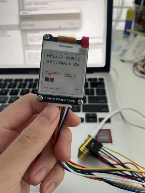
This project originally started with a BMP & an e-ink, but gradually didn't work for the use case. I have a cool e-ink now, though.
| Qty | Value | Footprint | References |
|---|---|---|---|
| 4 | MountingHole | MountingHole:MountingHole_2.2mm_M2_Pad | H1, H2, H3, H4 |
| 2 | LOGO | LOGO | G***, G*** |
| 2 | SW_Push | Button_Switch_THT:SW_PUSH_6mm | NEXT1, SELECT1 |
| 1 | 100K | Resistor_THT:R_Axial_DIN0207_L6.3mm_D2.5mm_P10.16mm_Horizontal | R1 |
| 1 | 1N4004 | Diode_THT:D_DO-41_SOD81_P10.16mm_Horizontal | D1 |
| 1 | 33K | Resistor_THT:R_Axial_DIN0207_L6.3mm_D2.5mm_P10.16mm_Horizontal | R2 |
| 1 | BME680 | Connector_PinSocket_2.54mm:PinSocket_1x06_P2.54mm_Vertical | J1 |
| 1 | Battery | Connector_JST:JST_PH_S2B-PH-K_1x02_P2.00mm_Horizontal | J5 |
| 1 | ST7789 | Connector_PinSocket_2.54mm:PinSocket_1x08_P2.54mm_Vertical | J3 |
| 1 | SW_SPDT | Button_Switch_THT:SW_Slide_SPDT_Angled_CK_OS102011MA1Q | SW1 |
| 1 | UPS | Connector_PinSocket_2.54mm:PinSocket_1x04_P2.54mm_Vertical | J6 |
| 1 | XIAO-ESP32-C6-DIP | Seeed_Studio_XIAO_Series:XIAO-ESP32-C6-DIP | U1 |

jfm92/everAliveSensor
Solar-powered BLE environmental sensor (temp, humidity, pressure) with a 50F supercapacitor — potentially infinite lifetime, 19-day dark autonomy. ESP32 + BME680. Experimental.


teapotlaboratories/bwlr3d
Teapot BWLR3D: Asset Tracker and Environmental Sensor with Solar Energy Harvesting


electronet-au/Smart-DoorWindow-sensor
Open source Smart door/window sensor. ESP32-C3 based with a custom power latch to obtain a deep sleep mode current of (30-60nA).
It measures 56.1 × 66.3 mm and has 2 copper layers, 1.6 mm thick.
17 parts, built around the BME680. The full list of its parts is on this page, with links to each part's symbol and footprint where PCBKit's library has them.
From the makrcat/EN.FO repository on GitHub, at the commit this page was made from: the board is pcb/thesensor.kicad_pcb and its schematic pcb/thesensor.kicad_sch. PCBKit opens the board in the browser, with nothing to install.
Its repository states no licence, so its author keeps all rights: ask makrcat before reusing the design.