4 layers20 × 140 mm

 makerspacelt/wiscale-mod-hw
This is ESP8266 and HX711 based weight monitoring device.
Wiscale mod is an open-source printed circuit board by makerspacelt, from the makerspacelt/wiscale-mod-hw repository on GitHub. It is a 2-layer board of 100 × 50 mm with 49 parts on 36 nets, routed with 277 tracks and 8 vias.
It is built around the WEMOS D1 MINI, DS18B20 and TPL5110DDC, with the AO3401A among its other parts. Its parts include 17 resistors, 11 capacitors, 5 ICs, 3 connectors and 2 transistors. It belongs with the ESP8266 boards of this library.


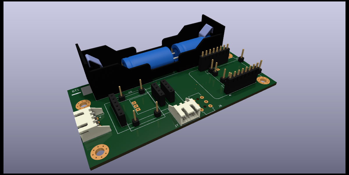
This is ESP8266 and HX711 based weight monitoring device.
Dev NOTE: before commit, run ./kibot.sh to regenerate documentation, bom, gerbers and other assets.
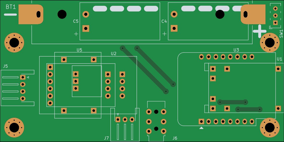
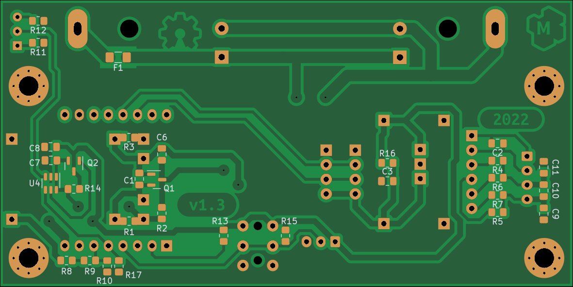
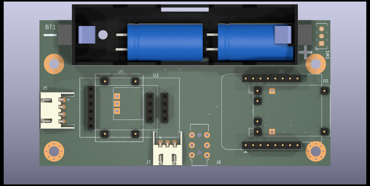
The circuit should be powered via a USB connector on the LiPo charger unless battery support and low-power sleep is not used.
Chargers(U1) with and without protection can be used. To use a charger without protection that does not have separate power output pins - R1 needs to be shorted out with a wire or zero ohms resistor.
For applications not requiring batteries whole LiPo charger section can be omitted including components U1,Q1,BT1,F1,C1,C4,C5,C6. That requires that the circuit be powered via a USB connector on the WeMos D1 mini module.
A timer is equipped with selectable(SW1) wake-up settings(R11 and R12).
For applications that do not require a low-power sleep timer can be bypassed by shorting out R14. Optionally components U3,C7,Q2,SW1,R11,R12 can be omitted in assembly.
Tests show that the circuit works down to about 2.7V without the need for boosting voltage for ADC. Following that - the boost converter(U5) can be omitted and R16 shorted out to bypass it.
To reduce noise on measurements capacitors(C9,C10,C11) on ADC input there placed. As a side effect, they slow down reading settling time after weight change. Removing these capacitors will give a fast reading but increase spread by about 3 times.
Populating all of the R4,R5,R6,R7 links gives the ability to choose an ADC amplifier and gain purely via software. What are the drawbacks of this approach are unclear to me but there is an option to disconnect unused amplifier by removing either R4 and R5 or R6 and R7 links.
| Qty | Value | Footprint | References |
|---|---|---|---|
| 6 | 100n | Capacitor_SMD:C_0805_2012Metric_Pad1.18x1.45mm_HandSolder | C2, C7, C8, C9, C10, C11 |
| 5 | DNP | Resistor_SMD:R_0805_2012Metric_Pad1.20x1.40mm_HandSolder | R1, R2, R3, R14, R16 |
| 4 | 0 | Resistor_SMD:R_0805_2012Metric_Pad1.20x1.40mm_HandSolder | R4, R5, R6, R7 |
| 4 | MountingHole_Pad | MountingHole:MountingHole_3.5mm_Pad_Via | H1, H2, H3, H4 |
| 3 | 10u | Capacitor_SMD:C_0805_2012Metric_Pad1.18x1.45mm_HandSolder | C1, C3, C6 |
| 3 | 15k | Resistor_SMD:R_0805_2012Metric_Pad1.20x1.40mm_HandSolder | R8, R9, R12 |
| 3 | 180k | Resistor_SMD:R_0805_2012Metric_Pad1.20x1.40mm_HandSolder | R10, R11, R13 |
| 2 | 4700u | -local:CP_Radial_D13.0mm_P5.00mm_L26.0mm | C4, C5 |
| 2 | 4k7 | Resistor_SMD:R_0805_2012Metric_Pad1.20x1.40mm_HandSolder | R15, R17 |
| 2 | AO3401A | Package_TO_SOT_SMD:SOT-23 | Q1, Q2 |
| 1 | 1A | Fuse:Fuse_1206_3216Metric_Pad1.42x1.75mm_HandSolder | F1 |
| 1 | ADC_HX711 | -local:module_adc_hx711_multi | U2 |
| 1 | BMS_USB_LiPo_Charger | -local:module_bms_usb_lipo_charger | U1 |
| 1 | DS18B20 | -local:Jack_3.5mm_Horizontal | J6 |
| 1 | DS18B20 | Connector_JST:JST_XH_S3B-XH-A-1_1x03_P2.50mm_Horizontal | J7 |
| 1 | G*** | kibuzzard-6343E0DF | kibuzzard-6343E0DF |
| 1 | G*** | kibuzzard-6352768B | kibuzzard-6352768B |
| 1 | LiPo | -local:BAT_BH-18650-PC | BT1 |
| 1 | Logo_Open_Hardware_Small | Symbol:OSHW-Symbol_6.7x6mm_Copper | LOGO2 |
| 1 | PSU_boost | -local:module_psu_boost | U5 |
| 1 | SW_SPDT | -local:SW_E-Switch_EG1271_DPDT | SW1 |
| 1 | TPL5110 | Package_TO_SOT_SMD:SOT-23-6 | U4 |
| 1 | WeMos_D1_mini | -local:WEMOS_D1_mini_light | U3 |
| 1 | cell | Connector_JST:JST_XH_S4B-XH-A-1_1x04_P2.50mm_Horizontal | J5 |
| 1 | logo_kms_small | -local:logo_kms_small_copper | LOGO1 |

makerspacelt/wiscale-hw
This is ESP8266 (ESP-12F) and HX711 based weight monitoring device.


bablokb/pcb-pico-proto-pboard
Plug&Play PCB for the Pico and Standard Hardware-Breakouts

unicab369/ESP-MESS
I am building a Wireless Bridge System that can manage multiple devices using a variety of wireless technologies.


Universidad-Cenfotec/Contraloria
Este es el resultado de un proyecto de investigación en coordinación con la Contraloría General de la República de Costa Rica y la cooperación alemana GIZ, para el desarrollo de cámaras IoT de bajo costo, que permitan…

CoreElectronics/CE-Makerverse-Nano-Power-Timer
This is the repo for the Core Electronics Makerverse Nano Power Timer.
It measures 100 × 50 mm and has 2 copper layers, 1.6 mm thick.
49 parts, built around the WEMOS D1 MINI, DS18B20, TPL5110DDC and AO3401A. The full list of its parts is on this page, with links to each part's symbol and footprint where PCBKit's library has them.
From the makerspacelt/wiscale-mod-hw repository on GitHub, at the commit this page was made from: the board is project/wiscale-mod.kicad_pcb and its schematic project/wiscale-mod.kicad_sch. PCBKit opens the board in the browser, with nothing to install.
Its repository states no licence, so its author keeps all rights: ask makerspacelt before reusing the design.