Skip to the content
PCBKitNew board
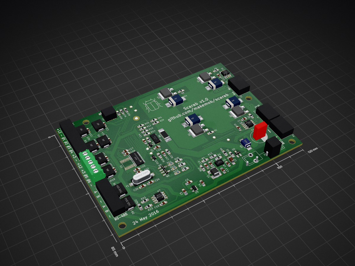
2 layers120 × 85 mmBugBridge, the printed circuit board in 3D

H-Bridge motor/actuator controller

Size
120 × 85 mm
Copper layers
2
Thickness
1.6 mm
Parts
112
Nets
64
Pads
307
Tracks, vias
1,073, 100
Pours
11
Routed
Yes
KiCad
KiCad 4
Created
25 May 2016
Updated
29 Dec 2018

Overview

BugBridge is an open-source printed circuit board by makemob, from the makemob/Scarab repository on GitHub, published under the CC-BY-SA-4.0 licence. It is a 2-layer board of 120 × 85 mm with 112 parts on 64 nets, routed with 1,073 tracks and 100 vias.

It is built around the LPC1114FDH28/102:5, MAX3485ED and MIC4605-1YM, with the TPS54061DRB, MIC5205-3.3YM5 and IPD35N10S3L-26 among its other parts. Its parts include 29 capacitors, 29 resistors, 19 diodes, 7 ICs and 7 connectors. It belongs with the robots and motor control boards and the NXP (LPC, Kinetis, i.MX RT) boards of this library.

Main components

9

README

README.md

Scarab

H-Bridge motor/actuator controller with RS-485 comms

  • Based around NXP LPC1114 Microcontroller
  • 13-48VDC input (36V nominal)
  • 8A average current output
  • 12VDC max 200mA auxiliary output
  • 3.3VDC auxiliary output ~40mA at 25 deg C, <10mA at 85 deg C
  • Good to 85 deg C ambient (in theory)
  • RS-485 comms, aux analog and digital I/O
  • 3 x indicator LEDs
  • NTC temperature sensor
  • Battery voltage sensing

All specifications are indicative..

Designed to drive Linak LA-35 linear actuators for the MakeMob UKI - Utility Kinetic Insect project http://makemob.net/portfolio_page/uki-electric-insect-vehicle/

Suitable for all kinds of other clever tricks

Firmware available at http://github.com/makemob/huhu

Licensed under Creative Commons Attribution Share Alike 4.0, https://creativecommons.org/licenses/by-sa/4.0/legalcode.txt

BOM adjustments since v1.0:

  • Replace R1, R2, R8, R9 with 100ohm
  • Populate D7 (3V zener), C14 (10nF), D15 & D16 (5V TVS), C25 & C26 (100nF)
  • RC snubber across motor output may be required to protect gate drivers from overvoltage (it is if you want to run LA-35 actuators at 36V..)

Next time:

  • Locating C1 closer to the bridge may improve transients
  • BAV99 footprints are wrong, need to jam them on sideways (D6, D7, D19)

Parts

112
QtyValueFootprintReferences
8NFResistors_SMD:R_0805_HandSolderingR3, R4, R10, R14, R20, R21, R22, R23
8NFCapacitors_SMD:C_0805_HandSolderingC3, C14, C19, C22, C25, C26, C27, C28
70RResistors_SMD:R_0805_HandSolderingR1, R2, R8, R9, R11, R15, R17
6NFBugBridgePCBLib:DO-214AC_HandsolderingD13, D14, D15, D16, D17, D18
4100nFCapacitors_SMD:C_0805_HandSolderingC15, C16, C17, C21
410nFCapacitors_SMD:C_0805_HandSolderingC8, C18, C23, C29
41uF 25V X7RCapacitors_SMD:C_0805_HandSolderingC6, C7, C11, C13
4IPD35N10S3L-26TO_SOT_Packages_SMD:TO-252-2LeadQ1, Q2, Q3, Q4
4NFDiodes_SMD:SMC_HandsolderingD1, D2, D3, D4
310kResistors_SMD:R_0805_HandSolderingR13, R28, R29
31k8Resistors_SMD:R_0805_HandSolderingR24, R25, R26
21uFCapacitors_SMD:C_0805_HandSolderingC4, C5
239pFCapacitors_SMD:C_0805_HandSolderingC20, C24
247kResistors_SMD:R_0805_HandSolderingR18, R19
2MIC4605-1YMBugBridgePCBLib:SOIC-8_Pitch1.27mmU5, U6
2MMUN2211LT1GTO_SOT_Packages_SMD:SOT-23_HandsolderingQ5, Q6
2TVS 12VBugBridgePCBLib:DO-214AC_HandsolderingD8, D9
10.01R 1WResistors_SMD:R_2512_HandSolderingR6
110uFCapacitors_SMD:C_0805_HandSolderingC12
1120kResistors_SMD:R_0805_HandSolderingR27
112MHz 20pFBugBridgePCBLib:Crystal_FOX_HCY1
1140kResistors_SMD:R_0805_HandSolderingR12
1150uFCapacitors_ThroughHole:C_Radial_D10_L20_P5C1
1158kResistors_SMD:R_0805_HandSolderingR7
11kResistors_SMD:R_0805_HandSolderingR16
12.2uFCapacitors_SMD:C_1206_HandSolderingC2
1220uH 1.57RBugBridgePCBLib:INDUCTOR_SDR0604L1
13VTO_SOT_Packages_SMD:SOT-23D19
168pFCapacitors_SMD:C_0805_HandSolderingC9
1750pFCapacitors_SMD:C_0805_HandSolderingC10
18ABugBridgePCBLib:Fuseholder_5x20_SchurterF1
197.6kResistors_SMD:R_0805_HandSolderingR5
1AUX_ABugBridgePCBLib:Connector_3.5mm_Pitch_8wayP4
1AUX_BBugBridgePCBLib:Connector_3.5mm_Pitch_5wayP5
1BATTBugBridgePCBLib:Connector_5.08mm_Pitch_2wayP1
1BAV99TO_SOT_Packages_SMD:SOT-23_HandsolderingD6
1BLUELEDs:LED_0805D11
1COMMSBugBridgePCBLib:Connector_3.5mm_Pitch_6wayP6
1GREENLEDs:LED_0805D12
1ISPBugBridgePCBLib:CON_02X05_1.27P7
1LPC1114FDH28/102BugBridgePCBLib:TSSOP-28U1
1MAX3485BugBridgePCBLib:SOIC-8_Pitch1.27mmU7
1MIC5205-3.3YM5TO_SOT_Packages_SMD:SOT-23-5U3
1MOTORBugBridgePCBLib:Connector_5.08mm_Pitch_2wayP2
1NFTO_SOT_Packages_SMD:SOT-23D7
1NTCS0805E3103JMTResistors_SMD:R_0805_HandSolderingTH1
1PASSTHRUBugBridgePCBLib:Connector_5.08mm_Pitch_2wayP3
1REDLEDs:LED_0805D10
1ST_CS70BugBridgePCBLib:TSSOP8U4
1TPS54061BugBridgePCBLib:VSON8U2
1TVSDiodes_SMD:SMB_HandsolderingD5

The 101 most common of 112 parts.

Questions

How big is the BugBridge PCB?

It measures 120 × 85 mm and has 2 copper layers, 1.6 mm thick.

What parts does the BugBridge use?

112 parts, built around the LPC1114FDH28/102:5, MAX3485ED, MIC4605-1YM and TPS54061DRB. The full list of its parts is on this page, with links to each part's symbol and footprint where PCBKit's library has them.

Where can I download the BugBridge KiCad files?

From the makemob/Scarab repository on GitHub, at the commit this page was made from: the board is v1.0/BugBridge.kicad_pcb. PCBKit opens the board in the browser, with nothing to install.

Can I use the BugBridge design in my own project?

Its repository publishes it under the CC-BY-SA-4.0 licence: you may reuse it on that licence's terms (keep the author's notice, and for a copyleft licence share your changes alike).

Similar boards

  • 4 layers56.3 × 39.7 mmFOC DualDRV8323, the printed circuit board in 3D

    FOC DualDRV8323

    totaldesaster/SimpleFOC-Serial-Driver

    Advanced dual BLDC driver based on the RP2350 and DRV8323S ICs, designed to be controlled from a trajectory controller over RS-485, RS-422 or TTL UART. Features a compact high power design with two stacked PCBs.

    66 parts1GPL-3.0
  • 4 layersMPPTSolarCharger, the printed circuit board in 3D

    MPPTSolarCharger

    SaintGimp/MPPTSolarCharger

    MPPT Solar battery charger

    45 parts1
  • 4 layers25.4 × 42.9 mmTESEO LIV3F uBUS, the printed circuit board in 3D

    TESEO LIV3F uBUS

    mkmielke/LIV3F_mikroBUS

    The KiCAD project files for a mikroBUS add-on board featuring the Teseo-LIV3F GNSS module.

    35 parts6
  • 4 layers180 × 110 mmPETER, the printed circuit board in 3D

    PETER

    dennowiggle/Retro-PETER

    3.3V Retro computer project => FPGA + RCBUS + CPU boards making a custom system.

    419 parts4LGPL-2.1
  • 4 layers65 × 40 mmHEXBERRY V-20Q100, the printed circuit board in 3D

    HEXBERRY V-20Q100

    logitiles/HEXBERRY-V-20Q100-0.91

    Open Hardware FPGA platform

    195 parts4CERN-OHL-S-2.0
  • 4 layers100 × 72 mmFLEADiP, the printed circuit board in 3D

    FLEADiP

    dennowiggle/FLEADiP

    FLEADiP is a compatiable add-on board for the Z80 Retro! project

    226 parts2LGPL-2.1
  • 4 layers85.3 × 78 mm2067-Z8S180, the printed circuit board in 3D

    2067-Z8S180

    dennowiggle/Z8S180-WTM

    Repository for sharing Z8S180-WTM design changes only. A private repository.

    53 parts1LGPL-2.1