2 layers

 madworx/tms5220-atmega2
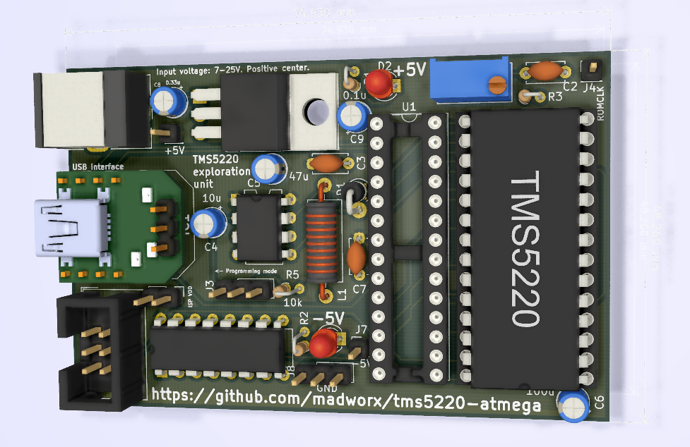
TMS5220 exploration unit
Tms5220-atmega is an open-source printed circuit board by madworx, from the madworx/tms5220-atmega repository on GitHub. It is a 2-layer board of 74.9 × 48.3 mm with 32 parts on 37 nets, routed with 306 tracks and 0 vias.
It is built around the ATMEGA328P-PU, UB232R and TPS6735D. Its parts include 8 capacitors, 8 connectors, 6 ICs, 5 resistors and 3 diodes. It belongs with the AVR (ATmega, ATtiny) and NXP (LPC, Kinetis, i.MX RT) boards of this library.

This project was created to try out the Texas Instruments TMS5220 Voice synthesis processor (of TI99/4A, Apple II Echo 2, and various pinball/arcade games fame).
First off, a word of warning: The PCB being powered by potentially three sources (PSU, Communication USB, AVR ISP), I've observed some weird behavior with power unexpectedly flowing in the wrong direction, causing intermittent system interruptions, host USB-port lock-up requiring system restart and one burnt MCU.
Preferably disconnect the PSU before connecting the ISP and move the J3 jumper to programming mode.
The project as it currently is is rather "build your own" but since the project was created to let me toy with the TMS5220 chip, it's not likely to see any major improvements in the forseeable future.
avrdudeavr-gccI used a cheap usbasp clone.
The UB232R interface needs to be configured using the FT_Prog tool:
High Current I/O's to be disabled.
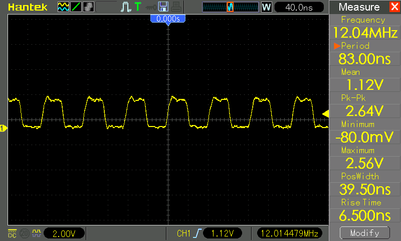
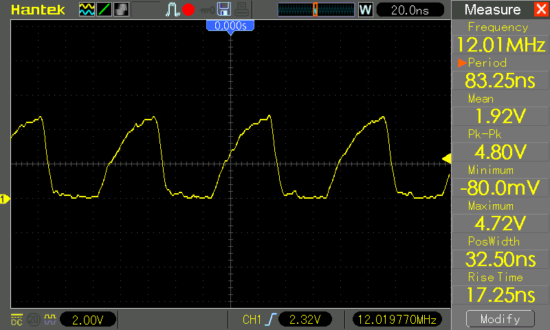
Under the IO Controls section, output on pin C0 should be set to CLK12, providing the Atmega 328P with a system clock of 12MHz.
The baud rate is the USB interface is configured by the host operating system driver. The MCU UART baud rate need to be matched to this.
lfuse should be programmed to external clock without /8DIV (0xE0):avrdude -p m328p -c usbasp -U lfuse:w:0xE0:m10-bit twos-complement.
|           |  PC latice outputs                                      |            |             |
|-----------|---------------------------------------------------------|------------|-------------|
| Value     |  YD  YC  YB  YA  Y9  Y8  Y7  Y6  Y5  Y4  Y3  Y2  Y1  Y0 | D/A input  | Analog (uA) |
|-----------|---------------------------------------------------------|------------|-------------|
| > +127    |  0   1   1   x   x   x   x   x   x   x   x   x   x   x  |  11111111  |      0      |
| > +127    |  0   1   0   x   x   x   x   x   x   x   x   x   x   x  |  11111111  |      0      |
| > +127    |  0   0   1   x   x   x   x   x   x   x   x   x   x   x  |  11111111  |      0      |
| +127      |  0   0   0   1   1   1   1   1   1   1   1   x   x   x  |  11111111  |      0      |
| +126      |  0   0   0   1   1   1   1   1   1   1   0   x   x   x  |  11111110  |      5.86   |
| etc.      |  0   0   0   .   .   .   .   .   .   .   .   x   x   x  |  ........  |     .....   |
| +1        |  0   0   0   0   0   0   0   0   0   0   1   x   x   x  |  10000001  |    738.00   |
| 0         |  0   0   0   0   0   0   0   0   0   0   0   x   x   x  |  10000000  |    744.00   |
| -1 (off)  |  1   1   1   1   1   1   1   1   1   1   1   x   x   x  |  01111111  |    750.00   |
| -2        |  1   1   1   1   1   1   1   1   1   1   0   x   x   x  |  01111110  |    755.80   |
| etc.      |  1   1   1   .   .   .   .   .   .   .   .   x   x   x  |  ........  |   .......   |
| -128      |  1   1   1   0   0   0   0   0   0   0   0   x   x   x  |  00000000  |   1500.00   |
| < -128    |  1   1   0   x   x   x   x   x   x   x   x   x   x   x  |  00000000  |   1500.00   |
| < -128    |  1   0   1   x   x   x   x   x   x   x   x   x   x   x  |  00000000  |   1500.00   |
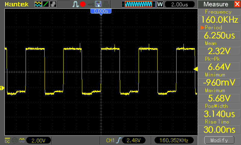
| < -128 | 1 0 0 x x x x x x x x x x x | 00000000 | 1500.00 |ROMCLK = 160kHz (= 6,26uS = 75x 12MHz cycles -> 37.5 cycles per level):T11 is pulled high before the start of each 10-bit word. (Note: The T11/IO cycle will run as long as the TMS chip is powered, regardless if any SPEAK or SPEAK EXTERNAL commands are currently running or not.) | 36| 36| 36| Clock cycles @ 12MHz
|
___ ___ ___ ___v ___ ___ ___ ___ ___ ___ ___ ___ ___
_| |___| |___| |___| |___| |___| |___| |___| |___| |___| |___| |___| |___| |___| *ROMCLK*
_______ :
_________| |___________:____________________________________________________________________________ *T11*
___:___________________________________________________________________________
_________________________| lsb | | | | | | | | | msb | *I/O*
^
|
+-- This is where we sample & store the value of I/O.TMS5220 flag us that it's ready to receive data with the use of the ~READY signal.
On negative edge trigger: Sample I/O pin, shift storage byte and add bit. (This should be in the range of ~15 instructions)
On positive edge trigger: Perform state-based logic (max ~35 clock cycles to complete each operation).
A full write of DBUS on the TMS requires us to write to three different ports on the Atmega. (~15 instructions each)
 $ setserial -a /dev/ttyUSB0 spd_cust
 $ setserial -a /dev/ttyUSB0 divisor 64 # for 375000
 $ setserial -a /dev/ttyUSB0 divisor 96 # for 250000
 $ stty -F /dev/ttyUSB0 38400
$ socat TCP-L:1147 FILE:/dev/ttyUSB0,b38400,raw,echo=0ROMCLK.PROMOUT pin to -5 to enable external clocking, removing timing constraints for the MCU.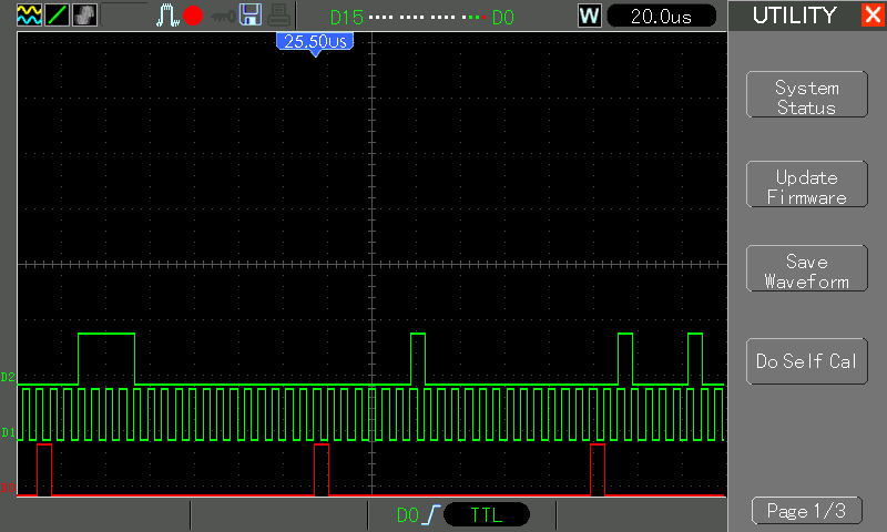
Connected to Atmega328P:
| Qty | Value | Footprint | References |
|---|---|---|---|
| 2 | 220 | Resistor_THT:R_Axial_DIN0204_L3.6mm_D1.6mm_P1.90mm_Vertical | R1, R2 |
| 2 | LED | LED_THT:LED_D3.0mm | D2, D3 |
| 1 | +5V | Connector_PinHeader_2.54mm:PinHeader_1x01_P2.54mm_Vertical | J6 |
| 1 | -5V | Connector_PinHeader_2.54mm:PinHeader_1x01_P2.54mm_Vertical | J7 |
| 1 | 0.1u | Capacitor_THT:CP_Radial_D4.0mm_P1.50mm | C9 |
| 1 | 0.33u | Capacitor_THT:CP_Radial_D4.0mm_P1.50mm | C8 |
| 1 | 100u | Capacitor_THT:CP_Radial_D4.0mm_P1.50mm | C6 |
| 1 | 10k | Resistor_THT:R_Axial_DIN0204_L3.6mm_D1.6mm_P1.90mm_Vertical | R5 |
| 1 | 10p | Capacitor_THT:C_Disc_D4.7mm_W2.5mm_P5.00mm | C2 |
| 1 | 10u | Capacitor_THT:CP_Radial_D4.0mm_P1.50mm | C4 |
| 1 | 10uH | Inductor_THT:L_Axial_L11.0mm_D4.5mm_P15.24mm_Horizontal_Fastron_MECC | L1 |
| 1 | 1u | Capacitor_THT:C_Disc_D4.7mm_W2.5mm_P5.00mm | C3 |
| 1 | 200k | Potentiometer_THT:Potentiometer_Bourns_3296W_Vertical | RV1 |
| 1 | 3k3 | Resistor_THT:R_Axial_DIN0204_L3.6mm_D1.6mm_P7.62mm_Horizontal | R4 |
| 1 | 47k | Resistor_THT:R_Axial_DIN0204_L3.6mm_D1.6mm_P1.90mm_Vertical | R3 |
| 1 | 47u | Capacitor_THT:C_Disc_D4.7mm_W2.5mm_P5.00mm | C7 |
| 1 | 47u | Capacitor_THT:CP_Radial_D4.0mm_P1.50mm | C5 |
| 1 | 74LS138 | Package_DIP:DIP-16_W7.62mm | U5 |
| 1 | ATmega328P-PU | Package_DIP:DIP-28_W7.62mm_Socket | U1 |
| 1 | AVR-ISP-6 | Connector_IDC:IDC-Header_2x03_P2.54mm_Vertical | J1 |
| 1 | Barrel_Jack_MountingPin | Connector_BarrelJack:BarrelJack_CUI_PJ-063AH_Horizontal | J2 |
| 1 | Conn_01x02 | Connector_PinHeader_2.54mm:PinHeader_1x02_P2.54mm_Vertical | J5 |
| 1 | Conn_01x03 | Connector_PinHeader_2.54mm:PinHeader_1x03_P2.54mm_Vertical | J3 |
| 1 | D_Schottky | Diode_THT:D_DO-41_SOD81_P2.54mm_Vertical_AnodeUp | D1 |
| 1 | GND | Connector_PinHeader_2.54mm:PinHeader_1x03_P2.54mm_Vertical | J8 |
| 1 | LM7805_TO220 | Package_TO_SOT_THT:TO-220-3_Horizontal_TabDown | U4 |
| 1 | ROMCLK | Connector_PinHeader_2.54mm:PinHeader_1x01_P2.54mm_Vertical | J4 |
| 1 | TMS5220 | Package_DIP:DIP-28_W15.24mm_Socket | U2 |
| 1 | TPS6735 | Package_DIP:DIP-8_W7.62mm | U3 |
| 1 | UB232R | UB232R:UB232R | IC1 |

zmaker/arduino_cookbook
gli sketch del nuovo progetto Arduino Cookbook e dei video di YouTube

coseyfannitutti/discipad
17-key numpad assembled with only through hole components, including usb type-c

matthewcieplak/super-sixteen
Code and schematics for the Super Sixteen Eurorack sequencer

coseyfannitutti/romeo
Staggered 40% keyboard pcb that can be assembled with only through hole components, including USB Type-C

mattybrad/drumkid
Version 4 was the first successful working design, with full code, schematics, Gerbers, etc available on GitHub.


leomil72/LM80C
A Z80-based homebrew computer withTMS9918, AY-3-8910, Z80 CTC, Z80 PIO, and Z80 SIO
It measures 74.9 × 48.3 mm and has 2 copper layers, 1.6 mm thick.
32 parts, built around the ATMEGA328P-PU, UB232R and TPS6735D. The full list of its parts is on this page, with links to each part's symbol and footprint where PCBKit's library has them.
From the madworx/tms5220-atmega repository on GitHub, at the commit this page was made from: the board is hardware/TMS5220-Atmega.kicad_pcb. PCBKit opens the board in the browser, with nothing to install.
Its repository states no licence, so its author keeps all rights: ask madworx before reusing the design.